
Control deck assembly
Please note: I did everything wrong, which is why the instructions don’t match many of the photos — I’m trying to save you a lot of heartache with instructions that are contrary to how I initially started. I found it most easy to do most of the work with the control panel leaning at an angle against my wall. Between my other obligations, it took several days to complete this part of the project.
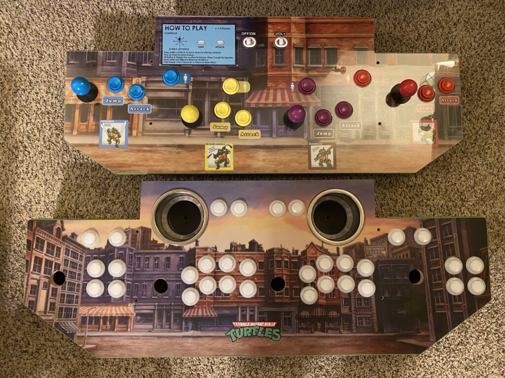
Besides more buttons for more games, if you compare the stock control deck to the one from X-99 Lives Arcade,
you’ll notice that with the replacement there’s more space for each player to stand shoulder-to-shoulder:
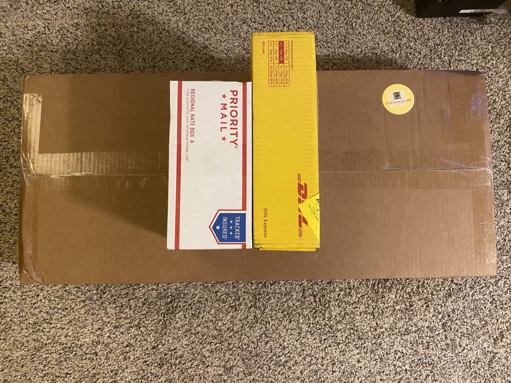
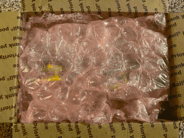
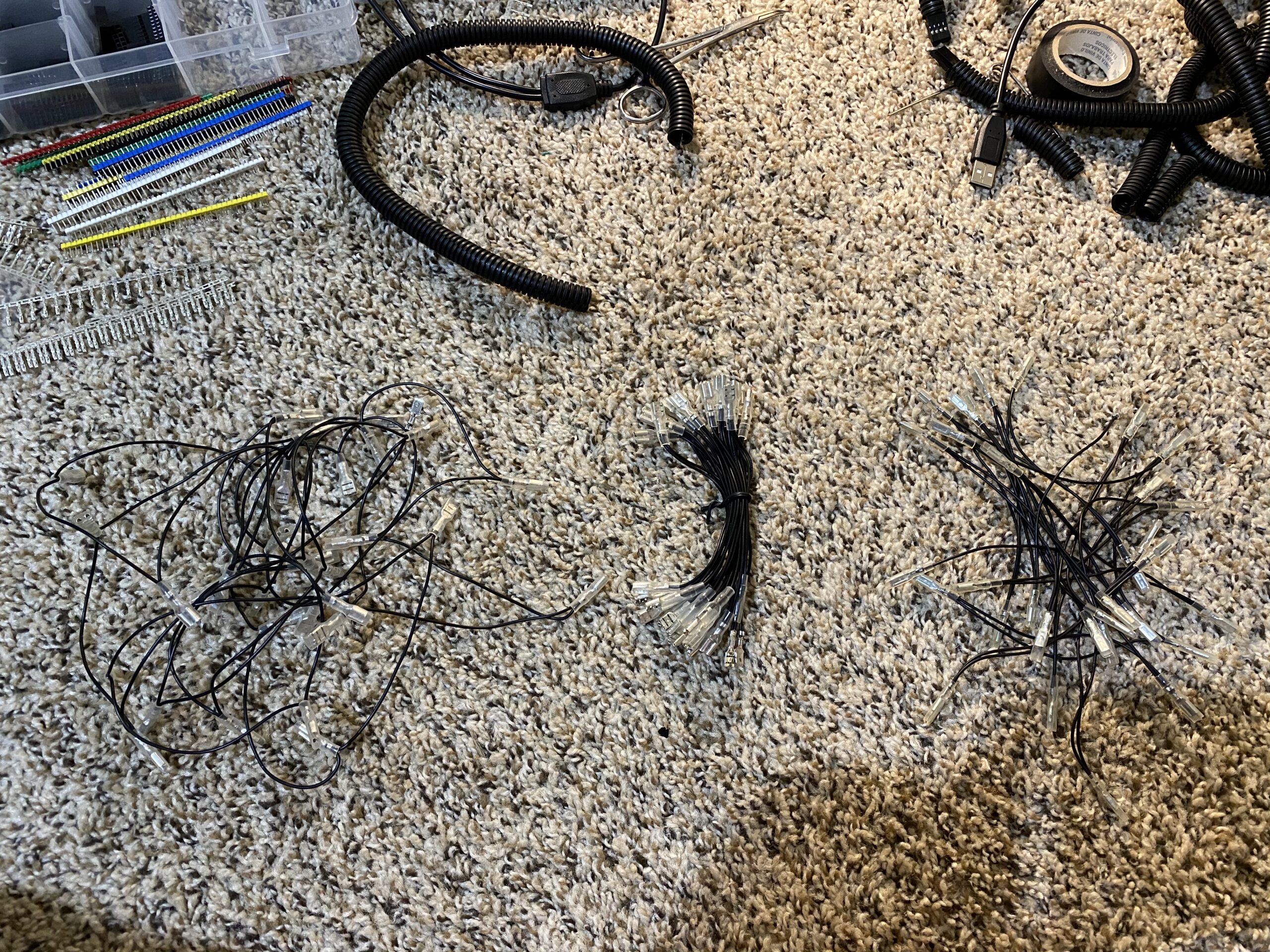
Unboxing the packages:
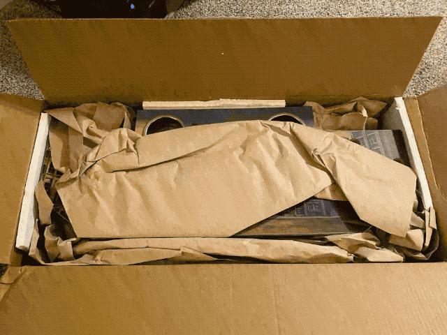
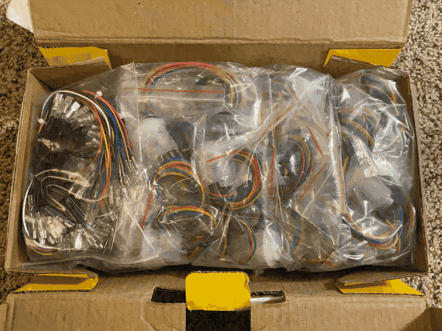
Count each of the parts from each of the boxes to ensure that you have received a full order:
- Control Deck
- 4 joysticks
- 32 buttons
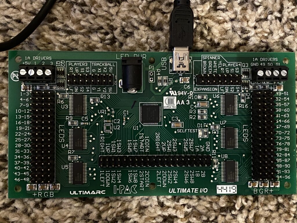
- Ultimarc I-PAC Ultimate I/O
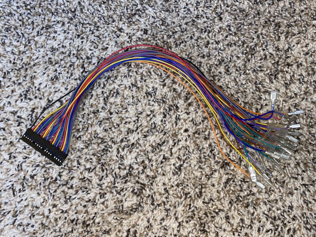
- Wire harness for players 1 & 2
- 2 wire harnesses for players 3 & 4
- 4 headers for players 3 & 4 pins
- 4 common ground wires (the 4th is slightly smaller than the rest)
- The “standard” and small size came with players 1 & 2
- The other 2 “standard” sizes are in addition for players 3 & 4
While many people recommend connecting the common ground wires first, I had better luck connecting the common ground wire after I connected everything else. Y.M.M.V.
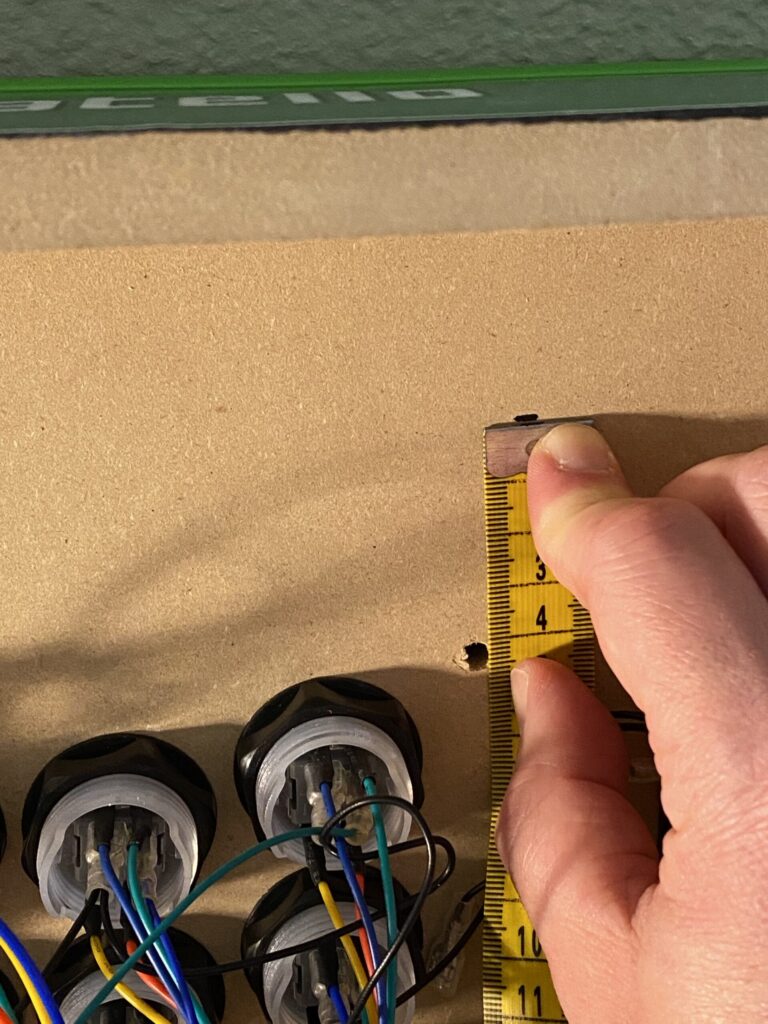
Remove the bottom covers on the left and right side, and then measure 4 CM distance from the bolt hole towards the front side of the control panel. Mark these two points with your permanent marker — this is so that you don’t place anything beneath these lines, which would be pinched by bolting this control deck to the cabinet.
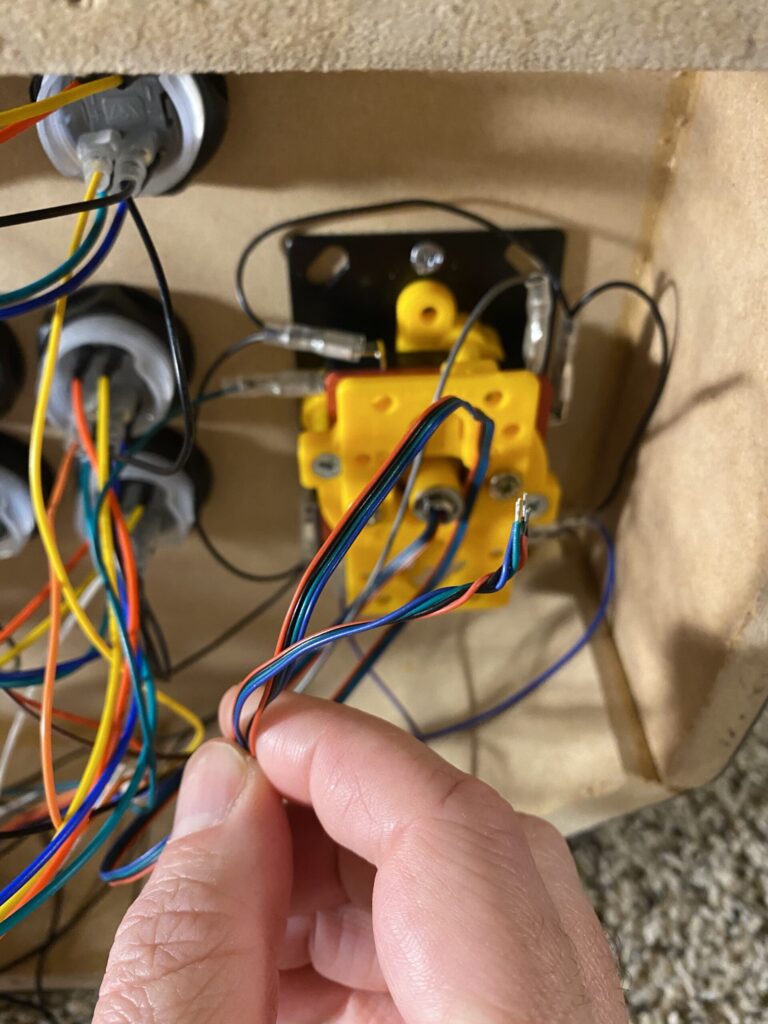
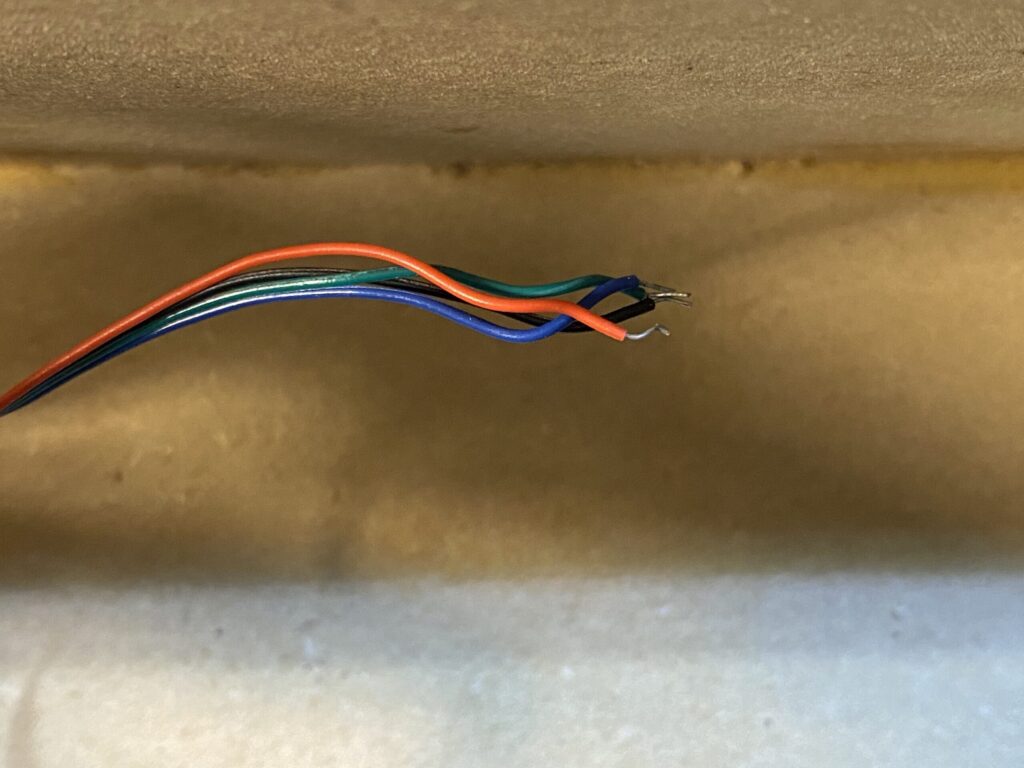
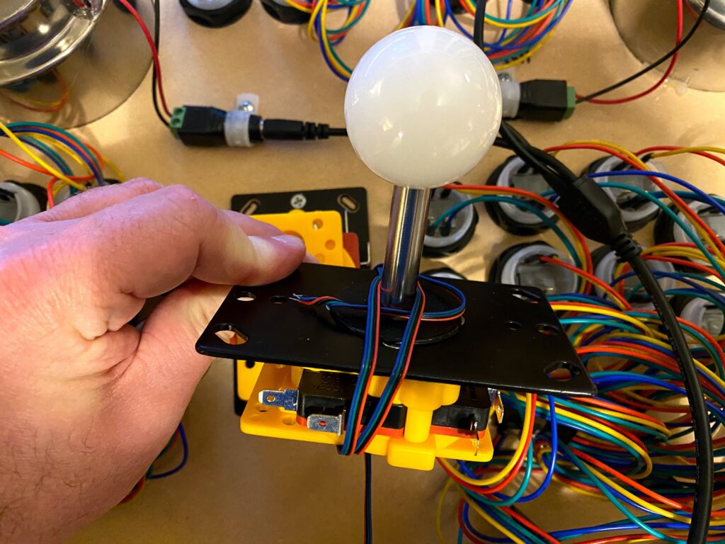
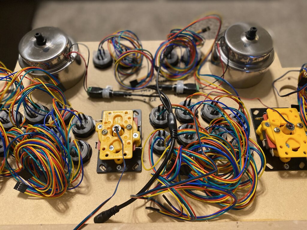
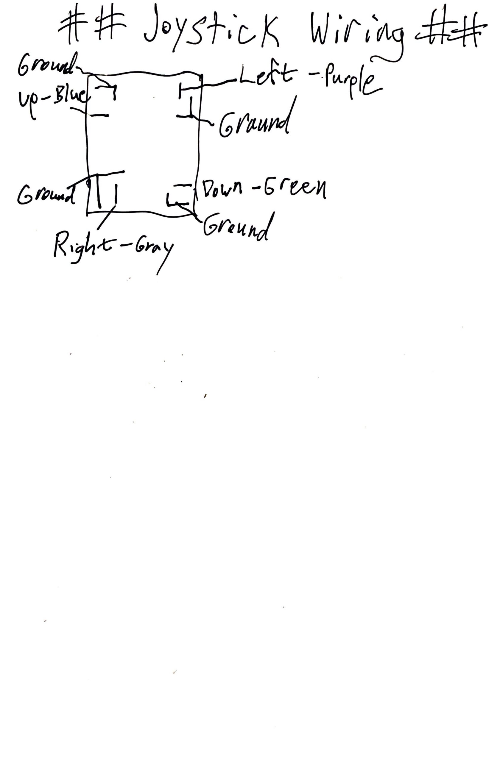
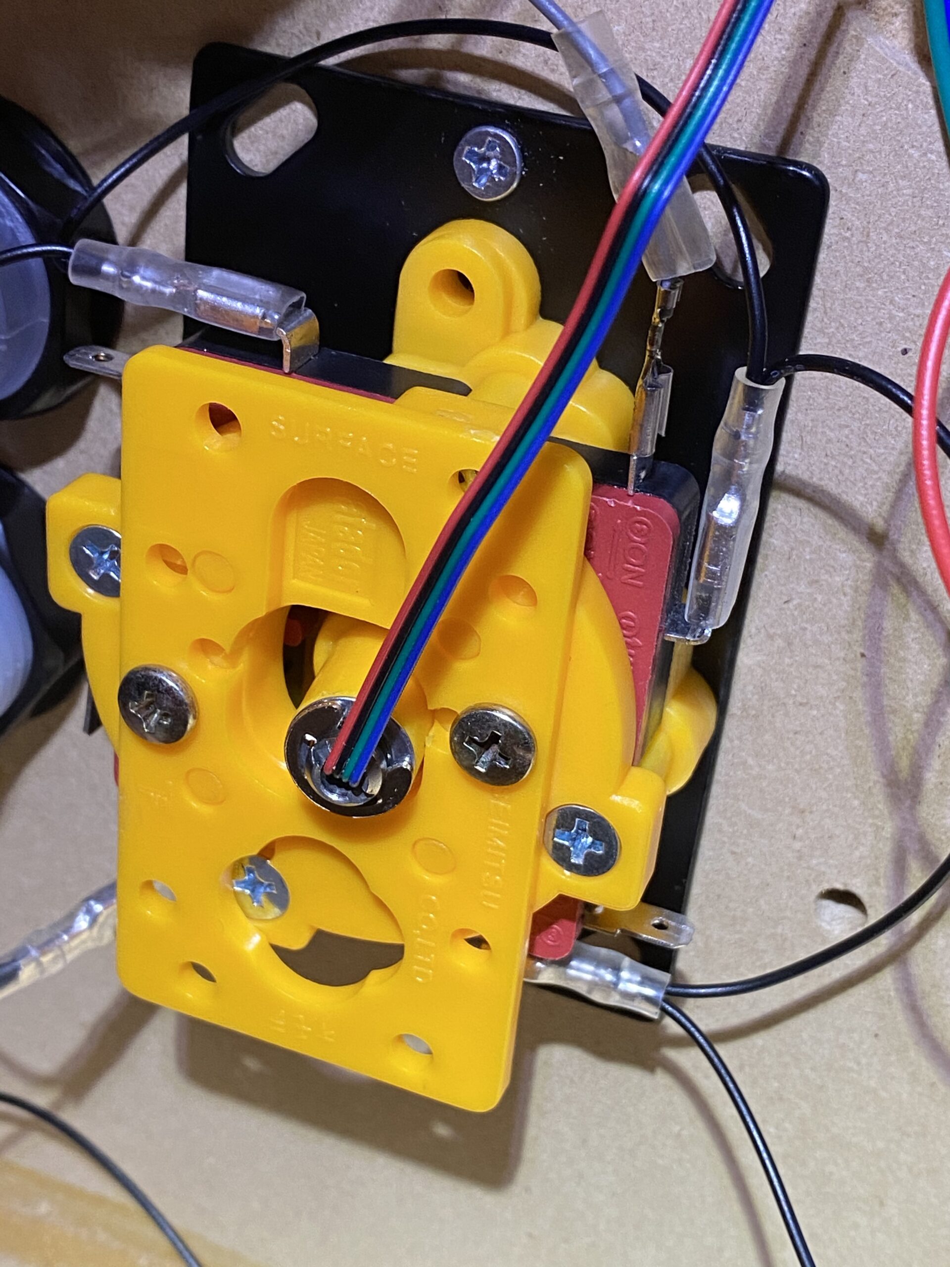
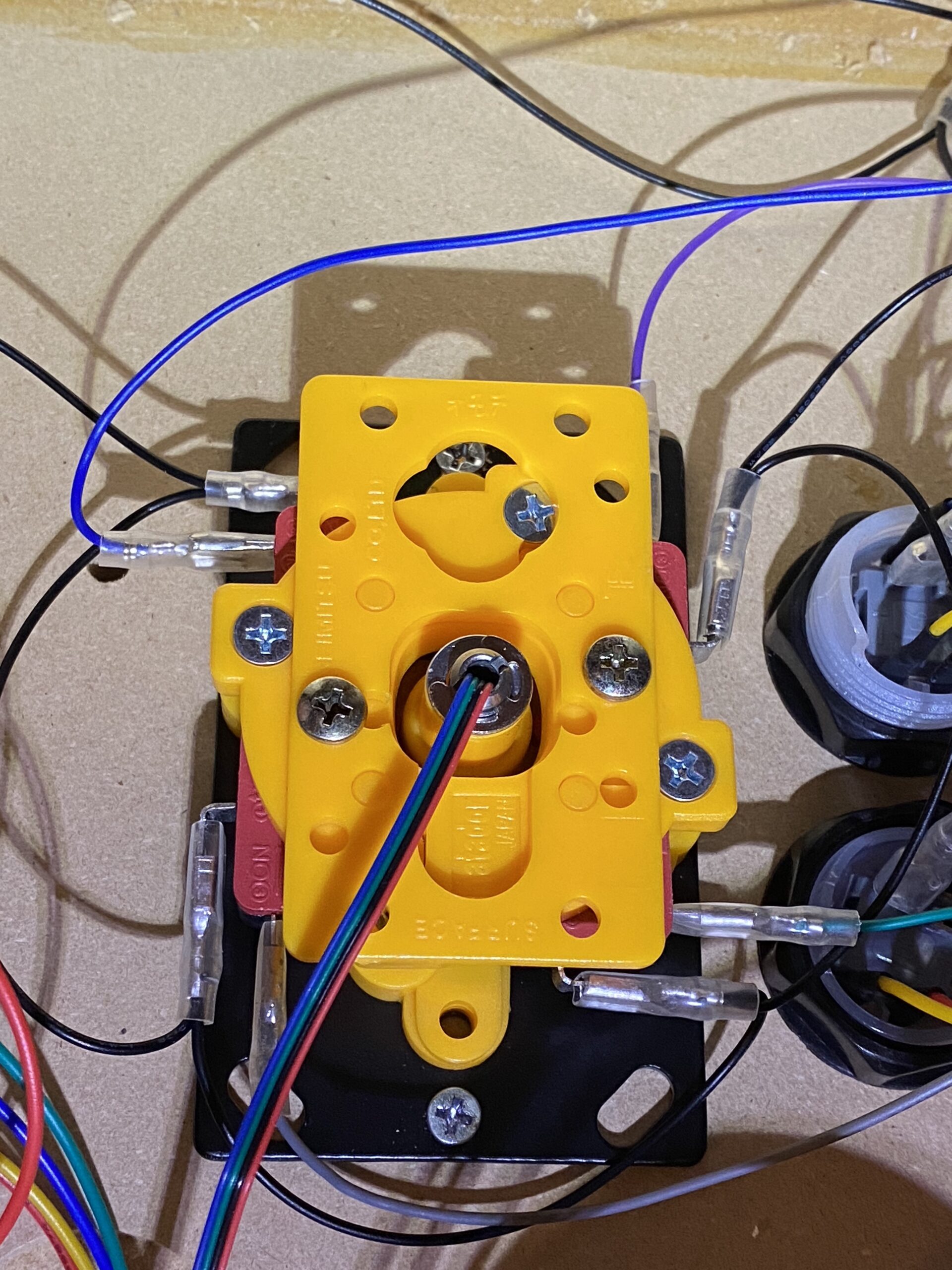
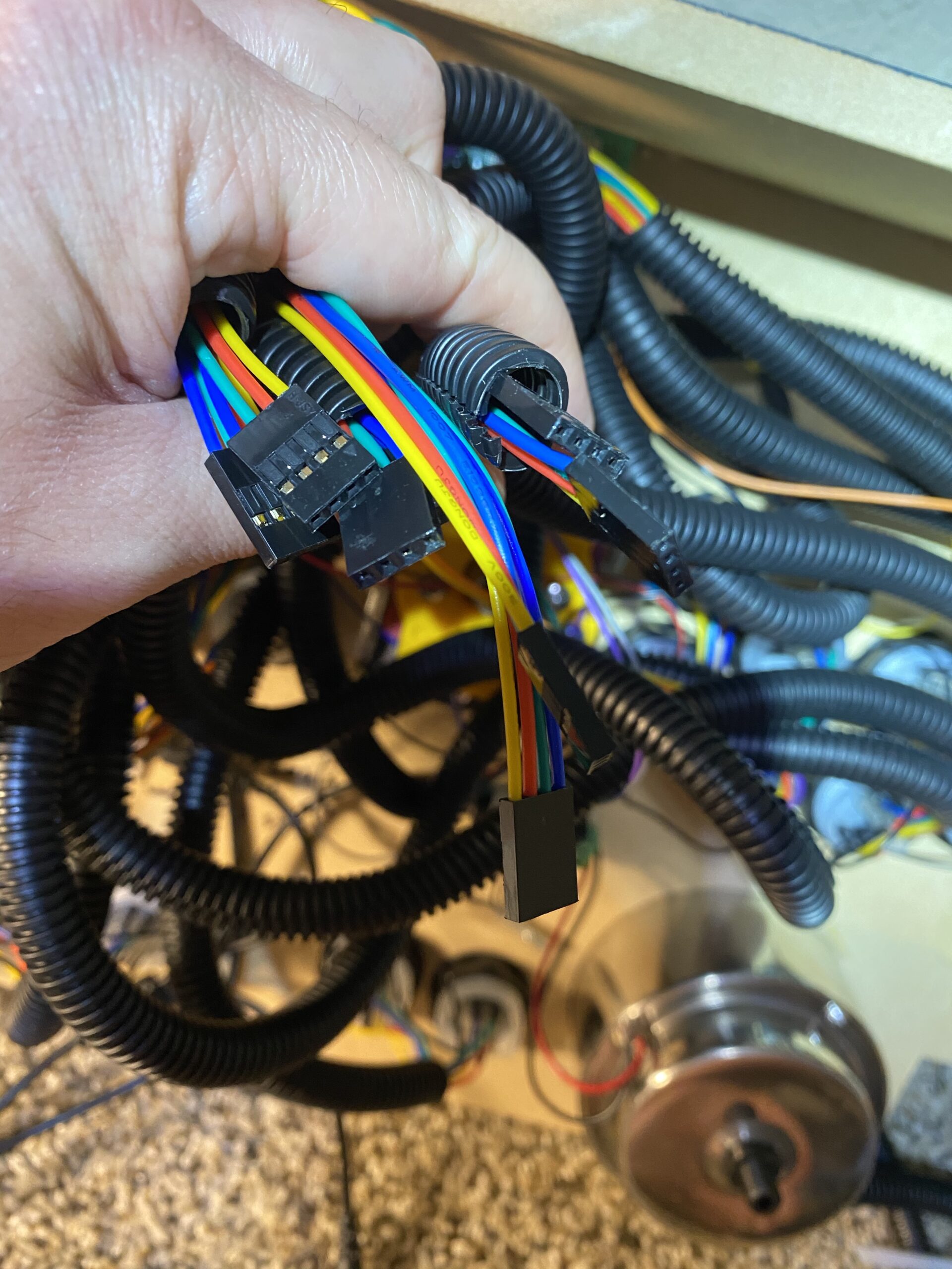
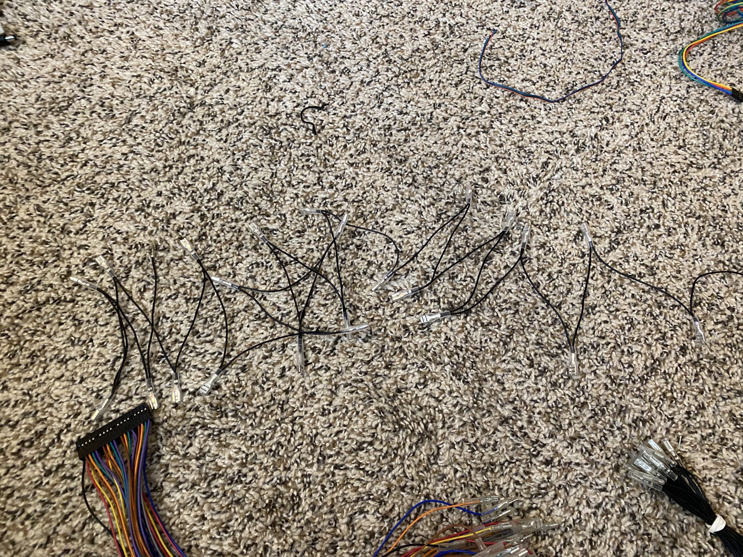
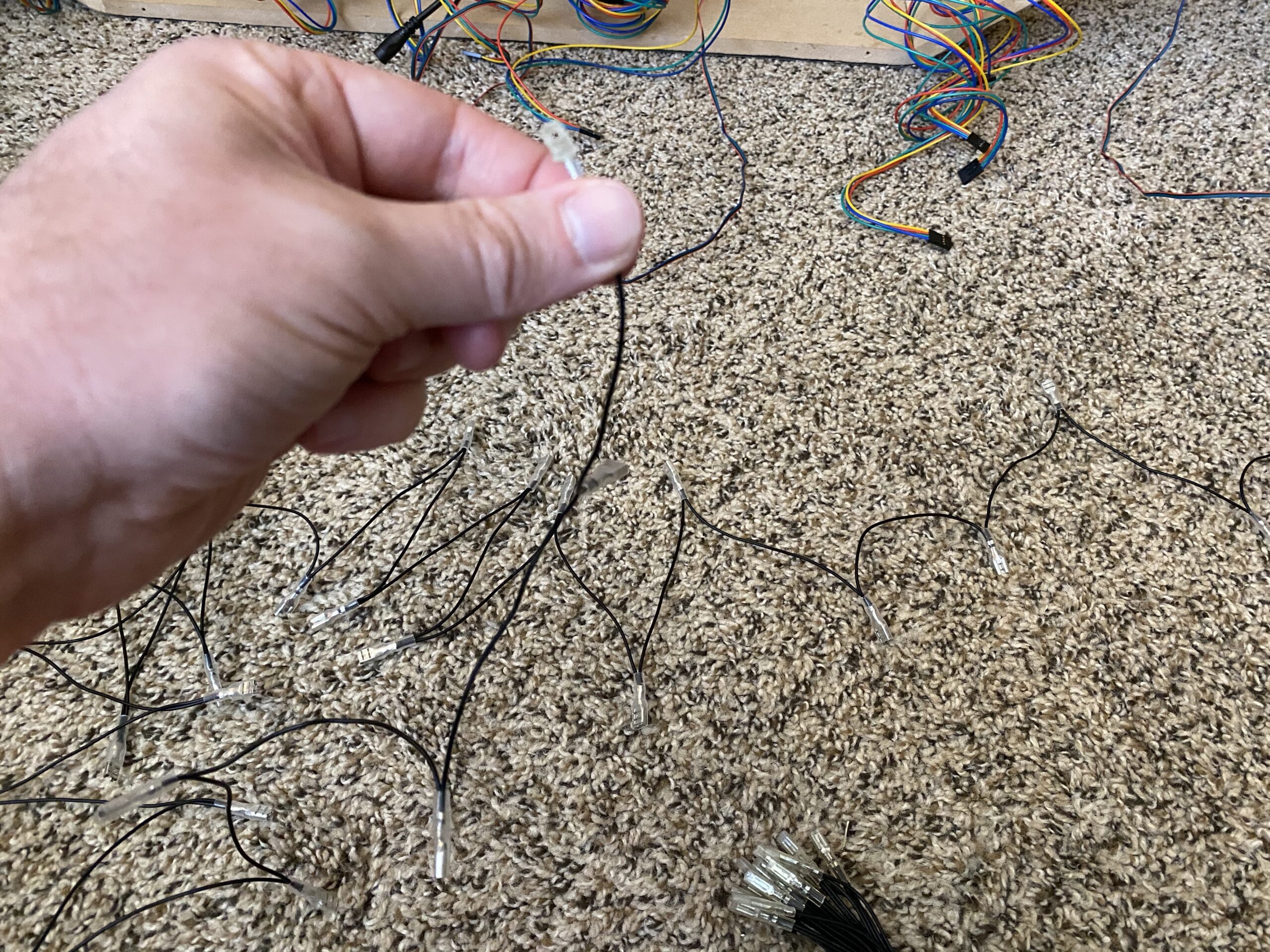
Add pins and then headers to each of the joysticks. These wires are very thin and difficult to work with. I had the best results when using the flat-head side of the glasses screwdriver to gently press each of the pins into the header.
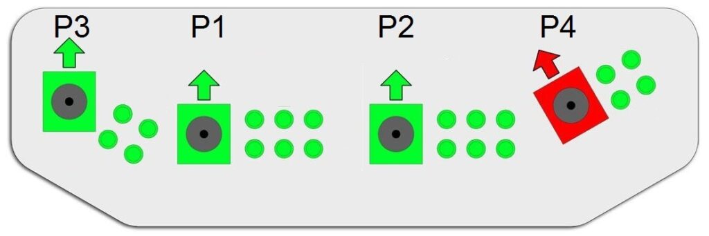
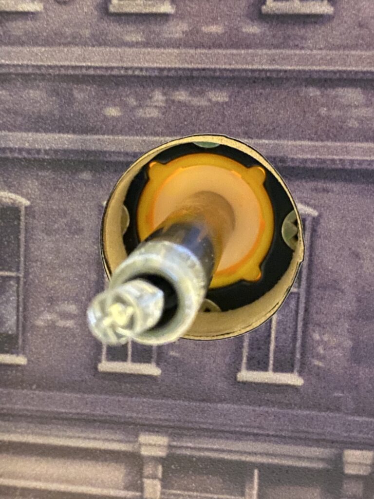
- Ultimarc’s support is the Arcade Controls Forum with a reciprocal Wiki. Mount your joysticks as the wiki dictates (green, not red).
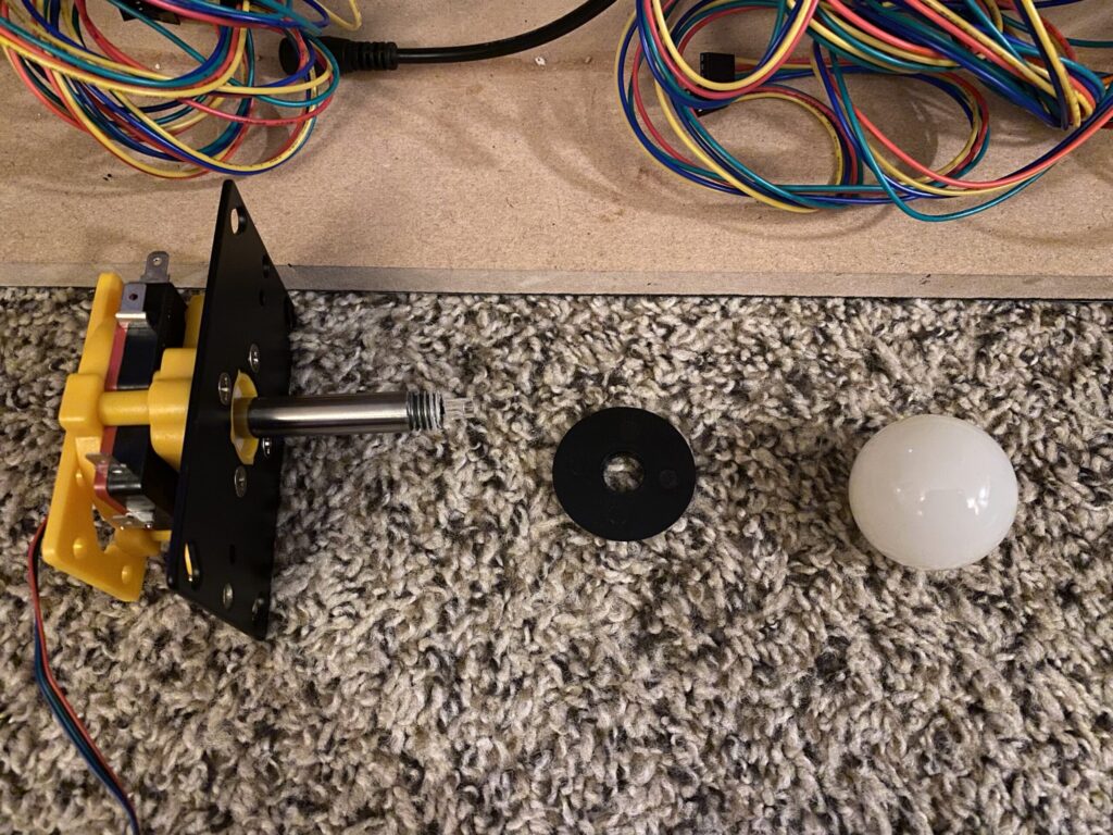
- Unscrew the joystick and align it (I used two side tables to hold the deck upside down).
- Align the joystick to be centered and pointing straight up and down (I used Allen Wrenches for positioning) and mark your points with a permanent marker.
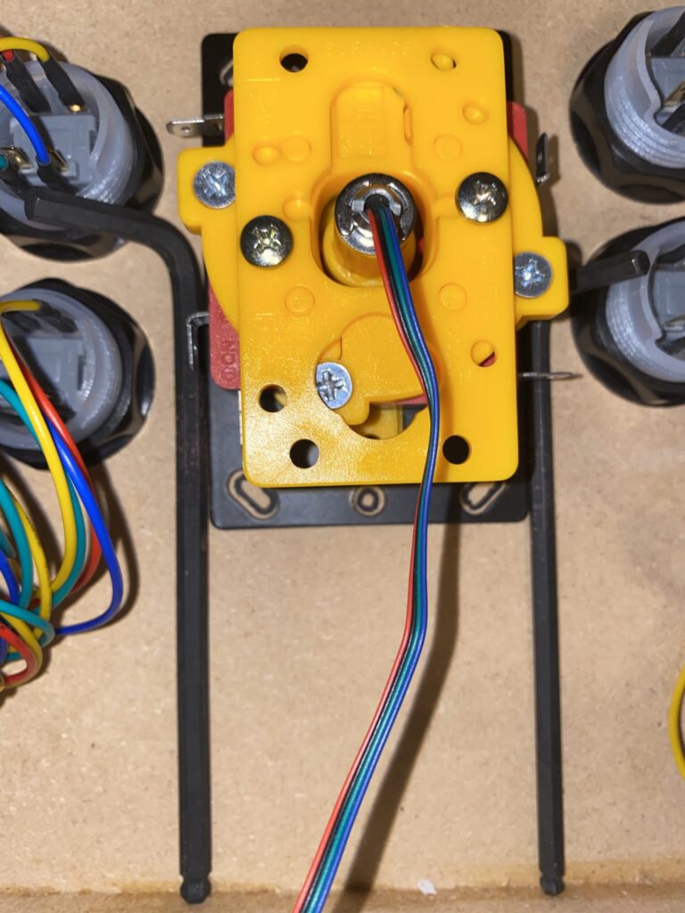
- Screw the joysticks into the deck using the short screws (you don’t want to pierce through the vinyl where your hands rest).
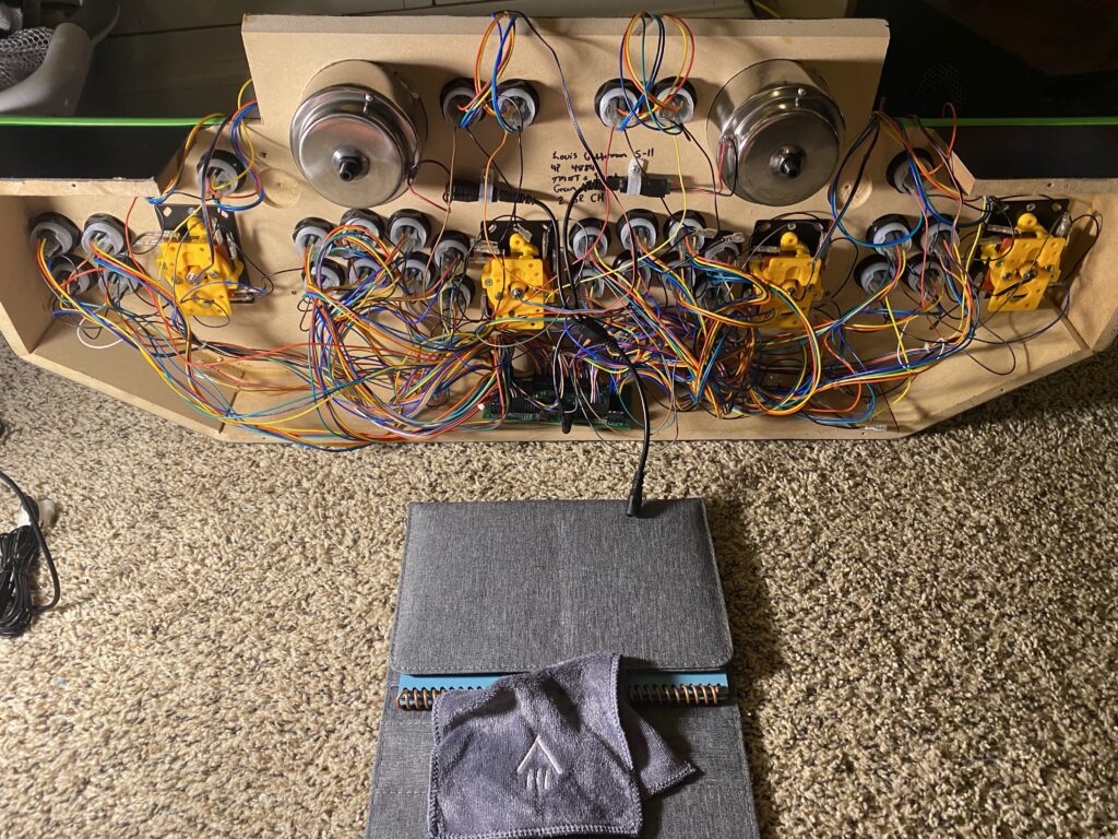
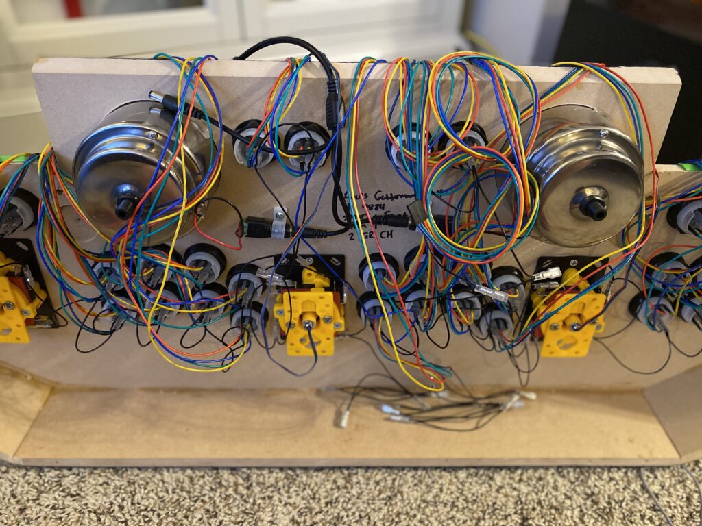
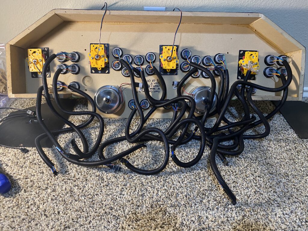
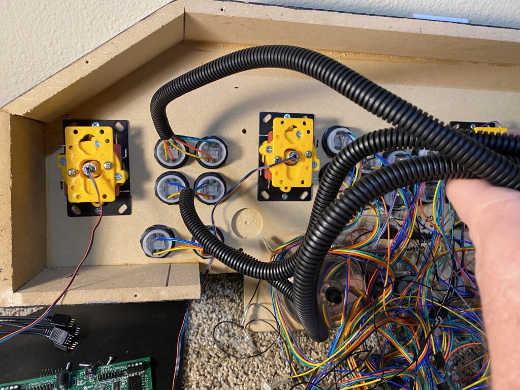
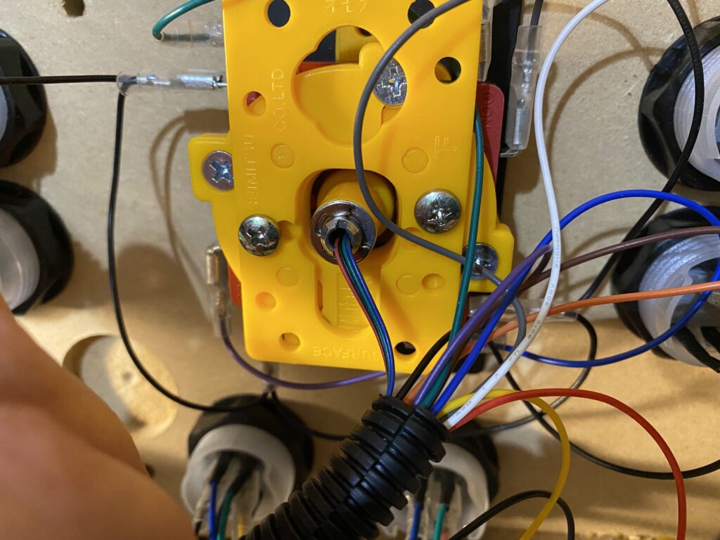


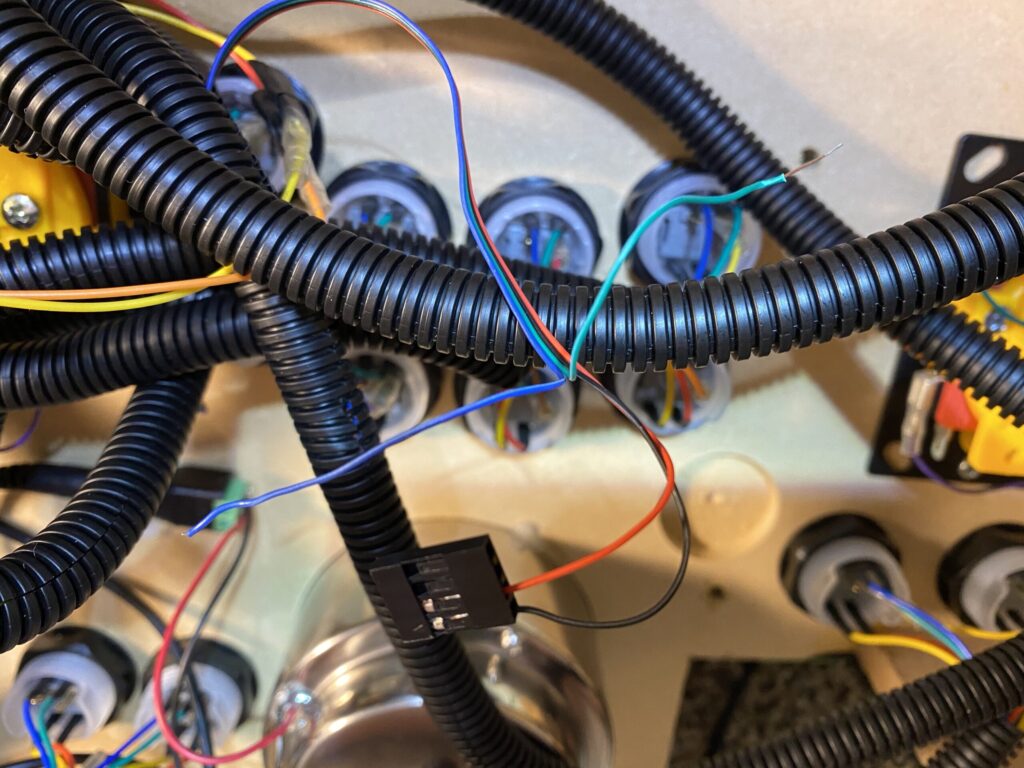
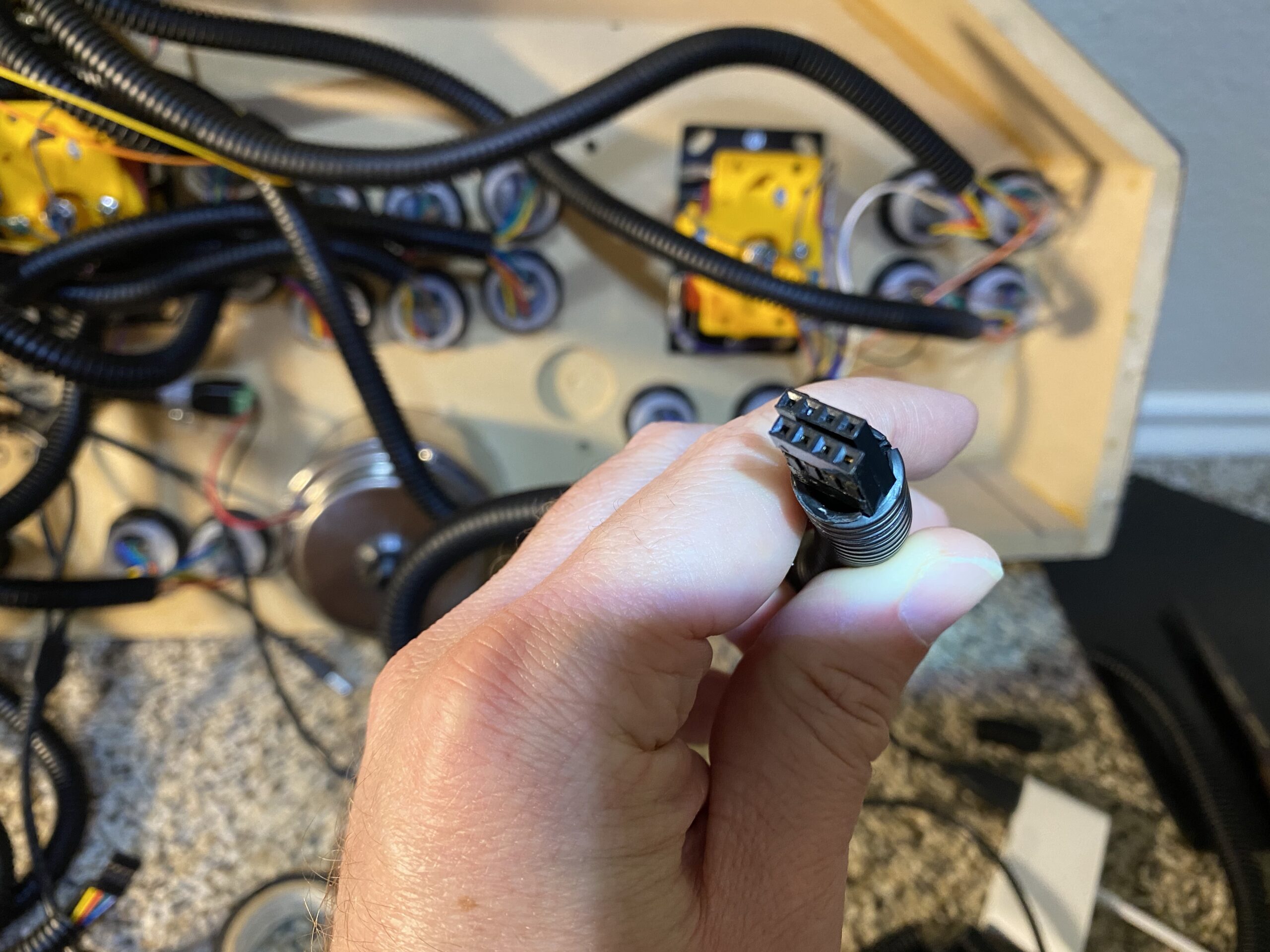
Wrap all of the wires in conduit. I found that the easiest way is to slide it on as close as I can to groups of devices (e.g. columns of buttons) guide the wire through the conduit slit, and work my way towards the Ultimarc MUC. From there, I cut the tube (while ensuring that I don’t cut the wires) and then and then start the process all over again for the next set.


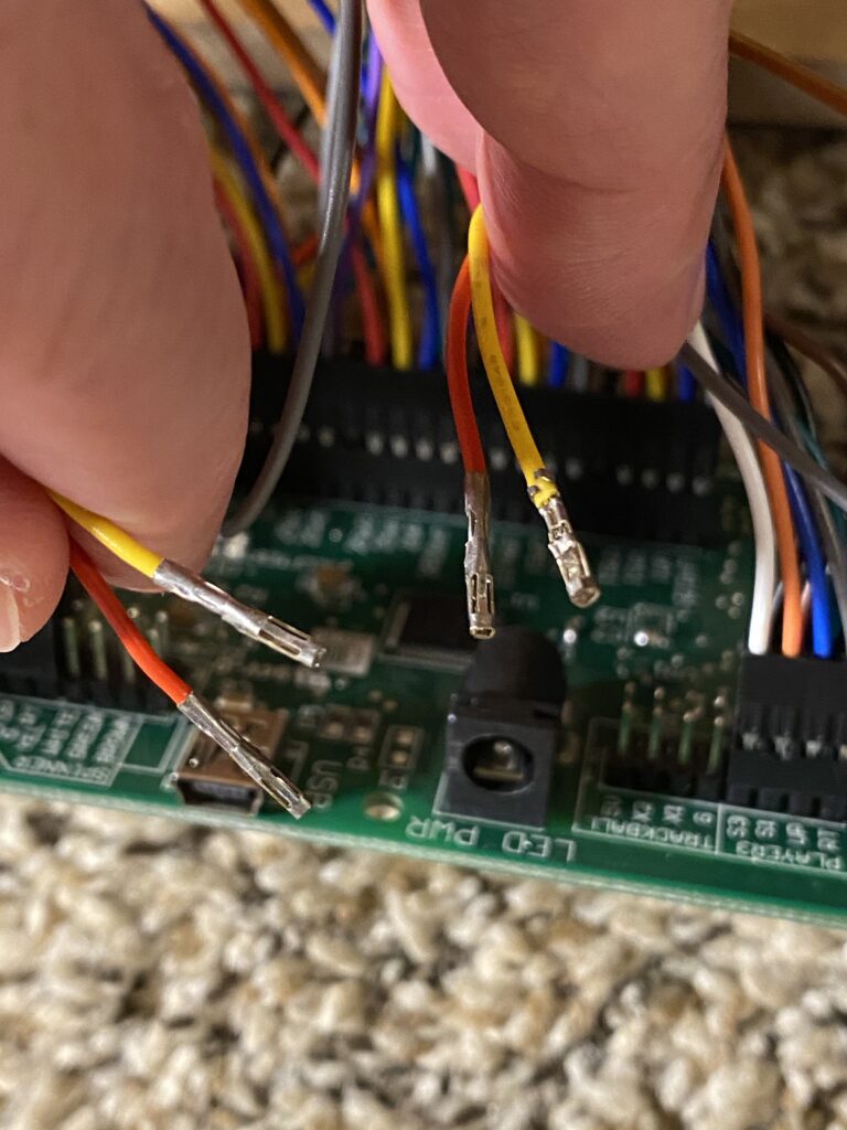
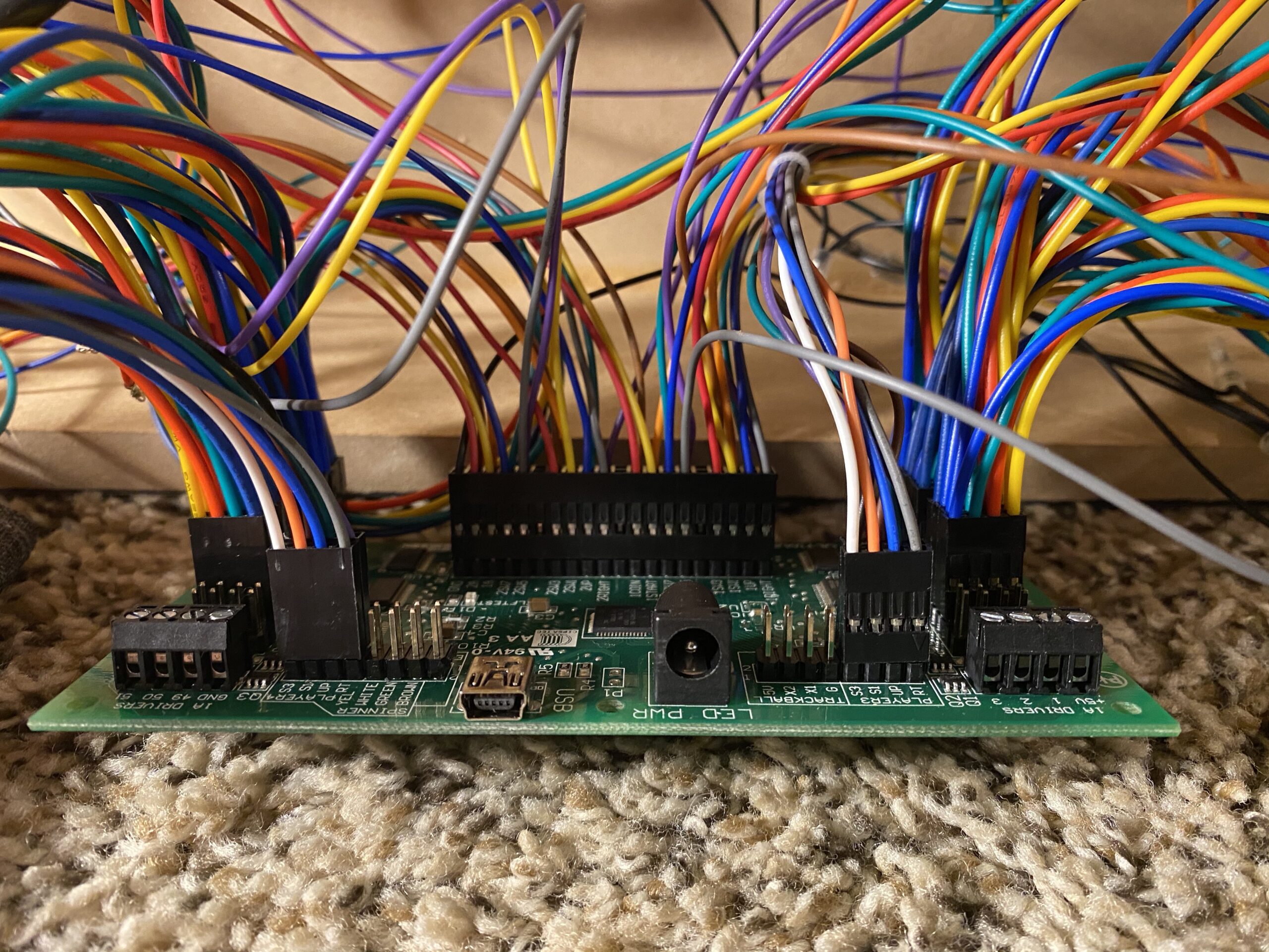
Mount the Ultimarc I-PAC Ultimate I/O MUC flush against the wall of the front of the panel while ensuring that the 5 Volt barrel and USB jacks will be able to be plugged into.
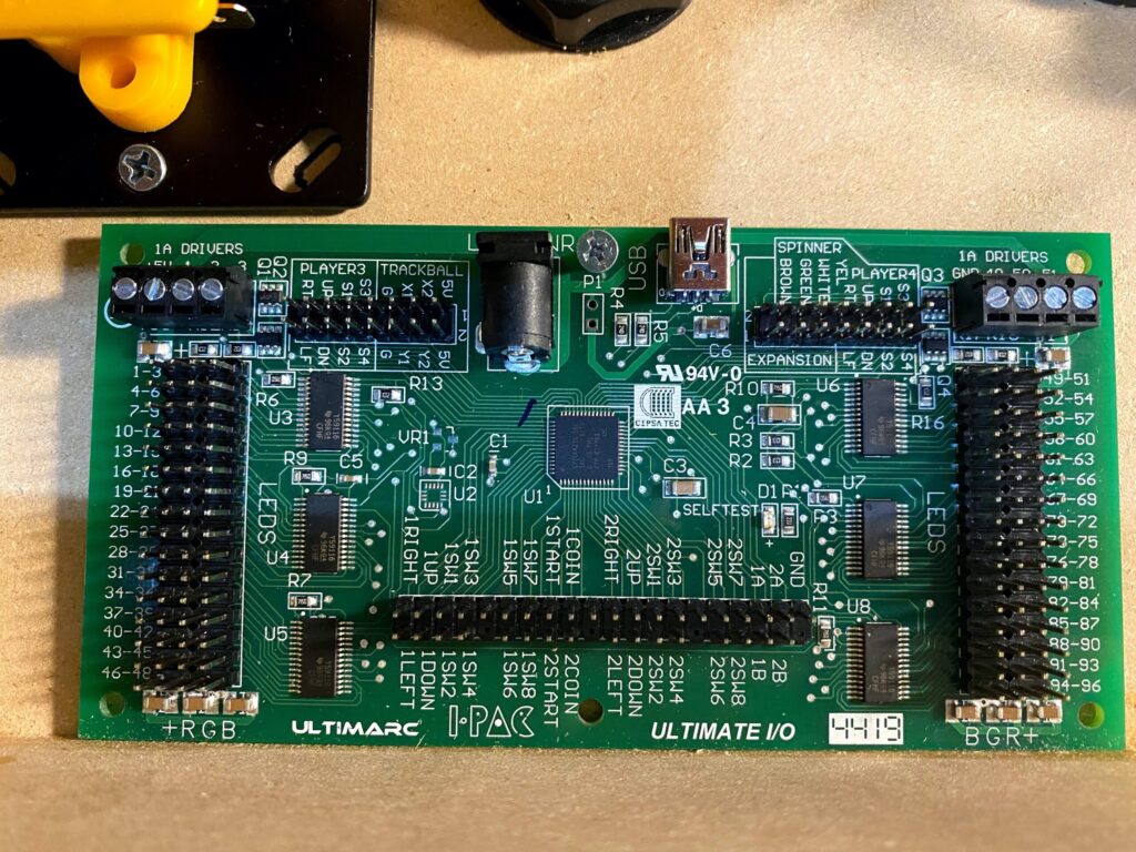
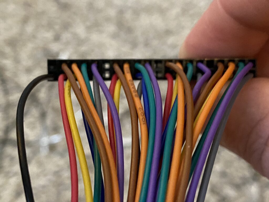
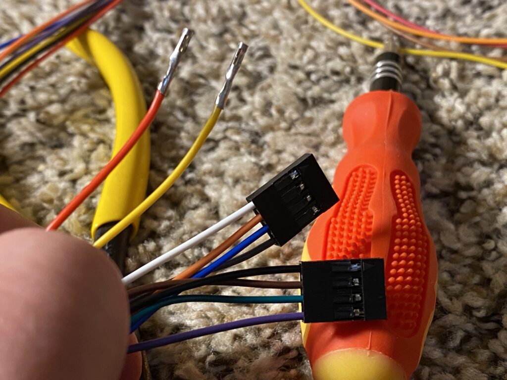
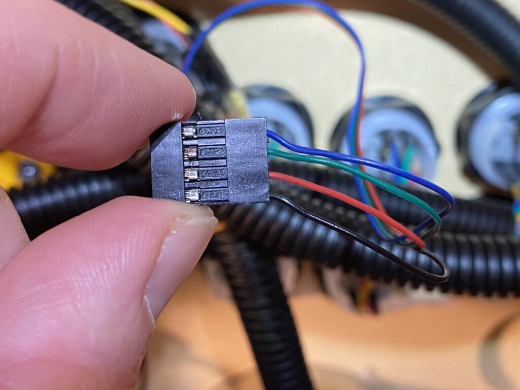
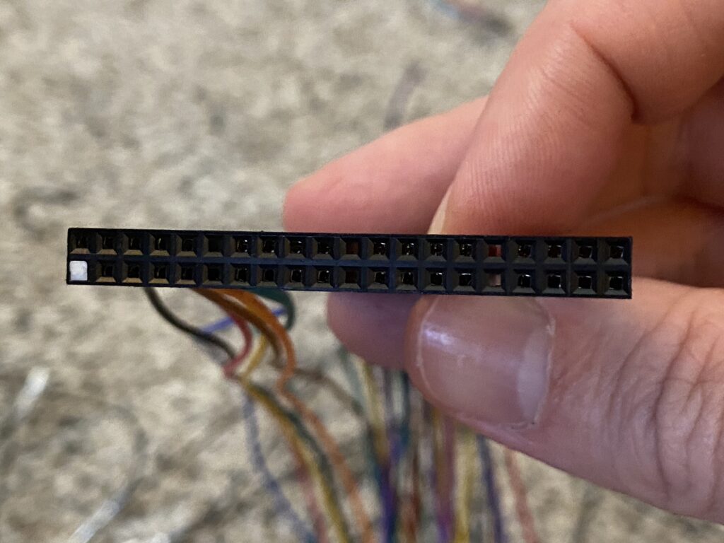
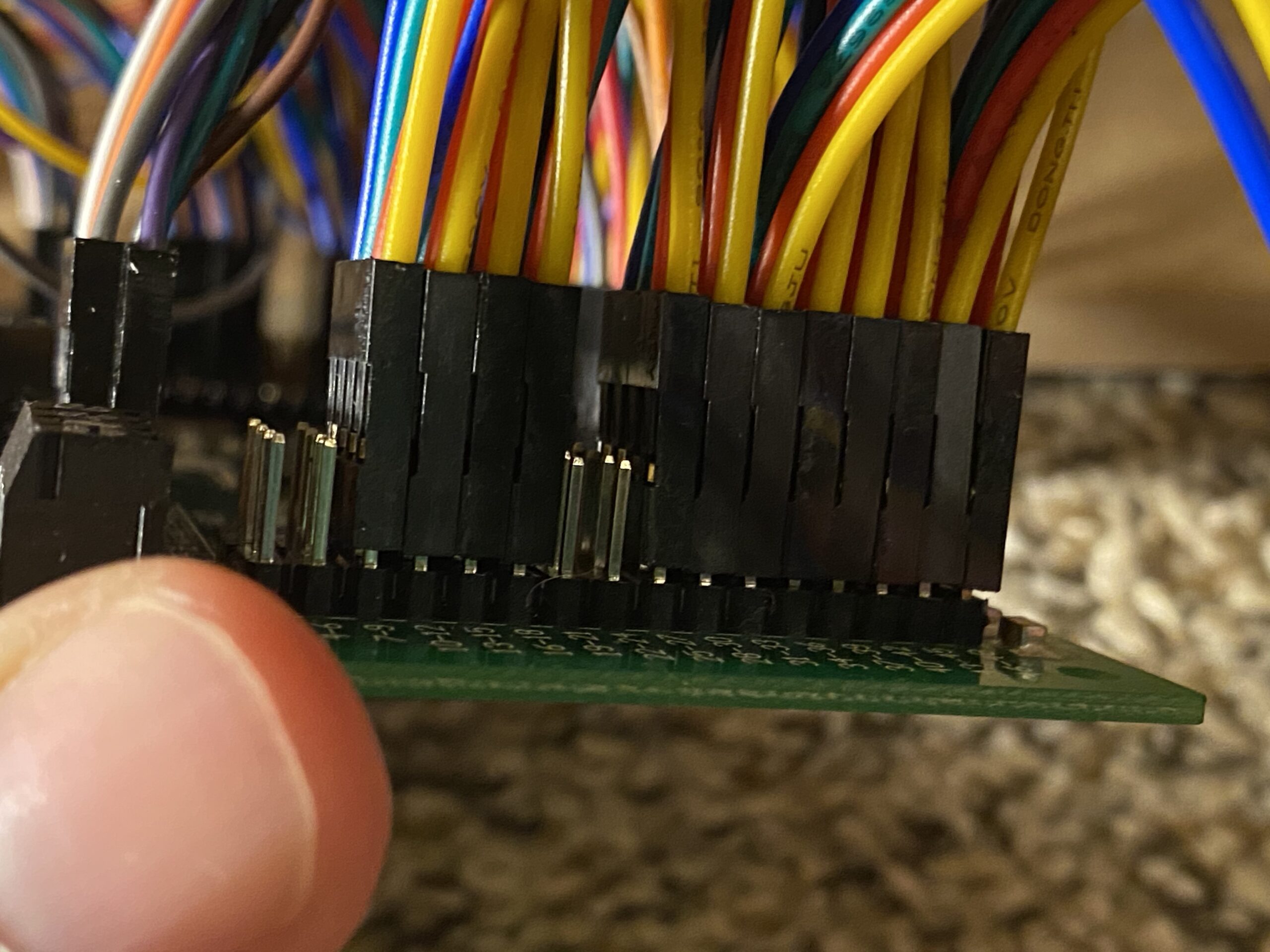
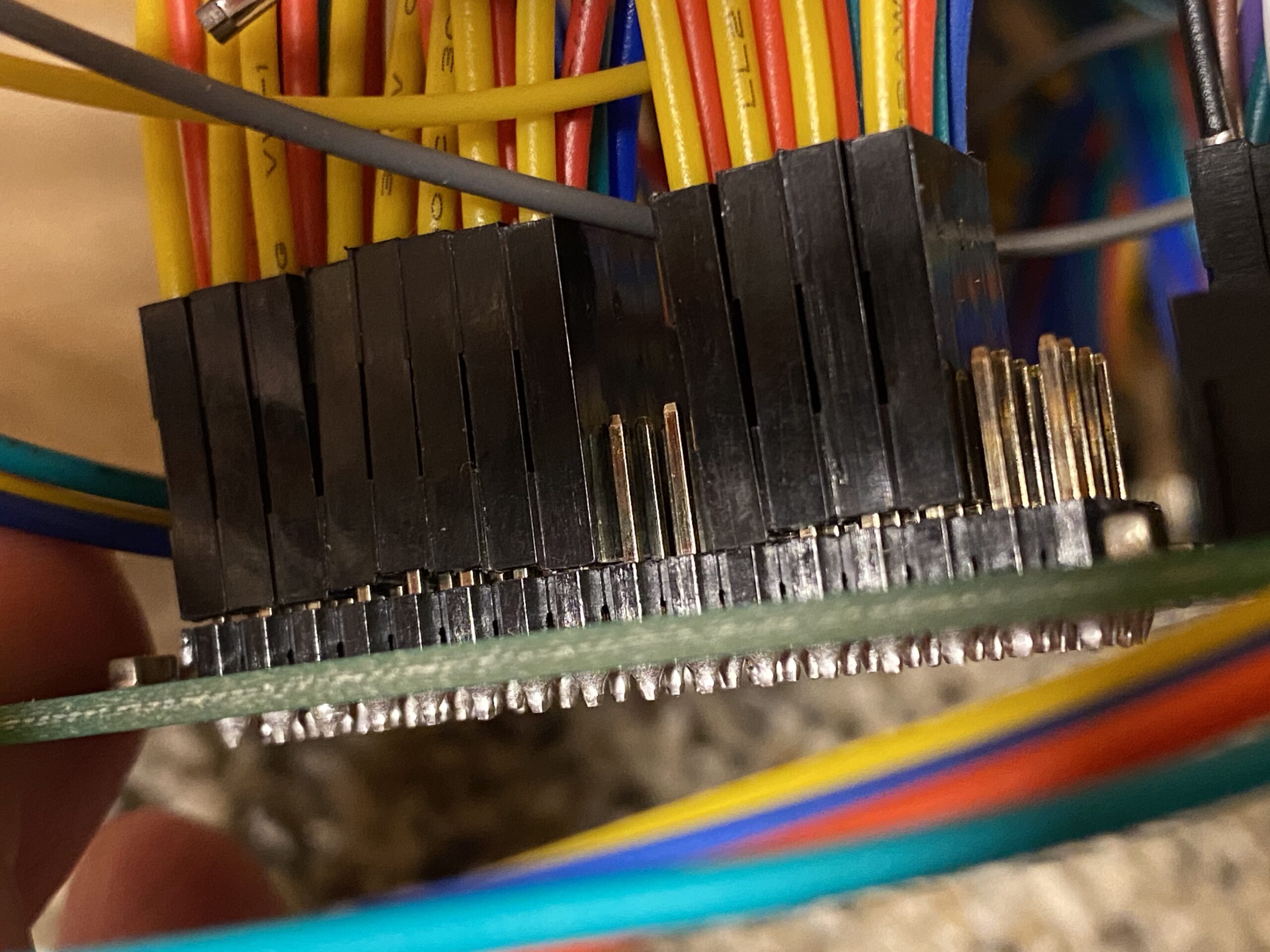
Using the Ultimarc MUC and players 1 & 2 harness as a reference and trying to match color positions, press the pins for players 3 and 4 into their reciprocal headers (2 headers for each player, so a total of 4 headers) to match that of the locations on the board.
You will have two pins left over for both player 3 and 4 (so a total of 4 pins) which you’ll tie into the main harness when all is said and done — I saved this for one of the last steps and used heat-shrink to connect them, and I used these 4 spare connectors for the “start” and “coin” buttons of players 3 & 4 (I repurposed the “coin” buttons to serve other functions since I have coin insert buttons beneath the control deck).
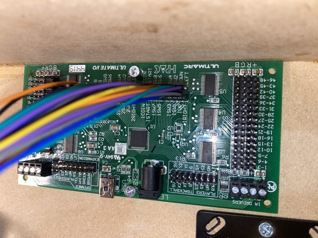
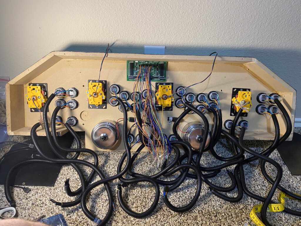
After you’ve connected the harnesses, run the harness wires through the conduits to their appropriate locations — for Players 3 & 4, I used the joystick conduits to carry the harness wires. Since these pins are programmatically mapped at both the board and the emulators, the order of the button pin (e.g. SW 1–8) doesn’t matter. I numbered button rows sequentially, so the top buttons of a player 1’s controls were SW 1–4 and the bottom buttons were SW 5–8, for example.
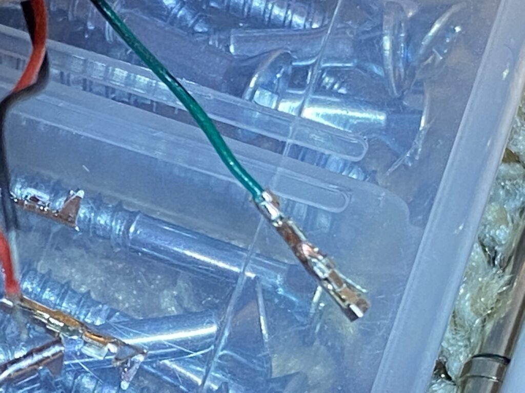
Each of the L-shaped pins is for the common ground wires, while as the straight pins are for the connectors from the harness.
Remember the spare pins from the harnesses for Players 3 & 4? I could’ve created an adapter cable, but I didn’t want one more point of failure that I’d have to worry about when mounting the deck.
I ran these along the top of the conduit, placed these pins into the nook of the auxiliary terminals from the harness for Players 1 & 2 (1A, 2A, 1B, and 2B that are all beneath the GND pin on the board), used heat-shrink to seal them in place, and then zip-tied them to the top of the conduit.
Photos of LED splitters goes here.
Instructions for LED splitters goes here.
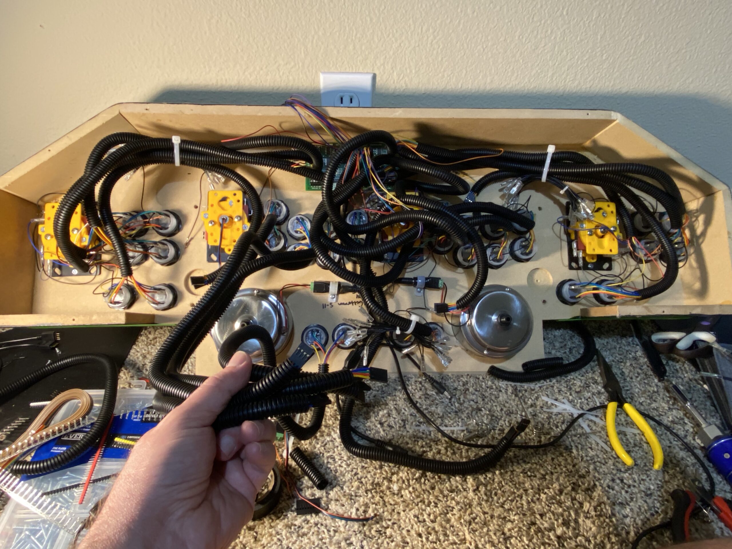
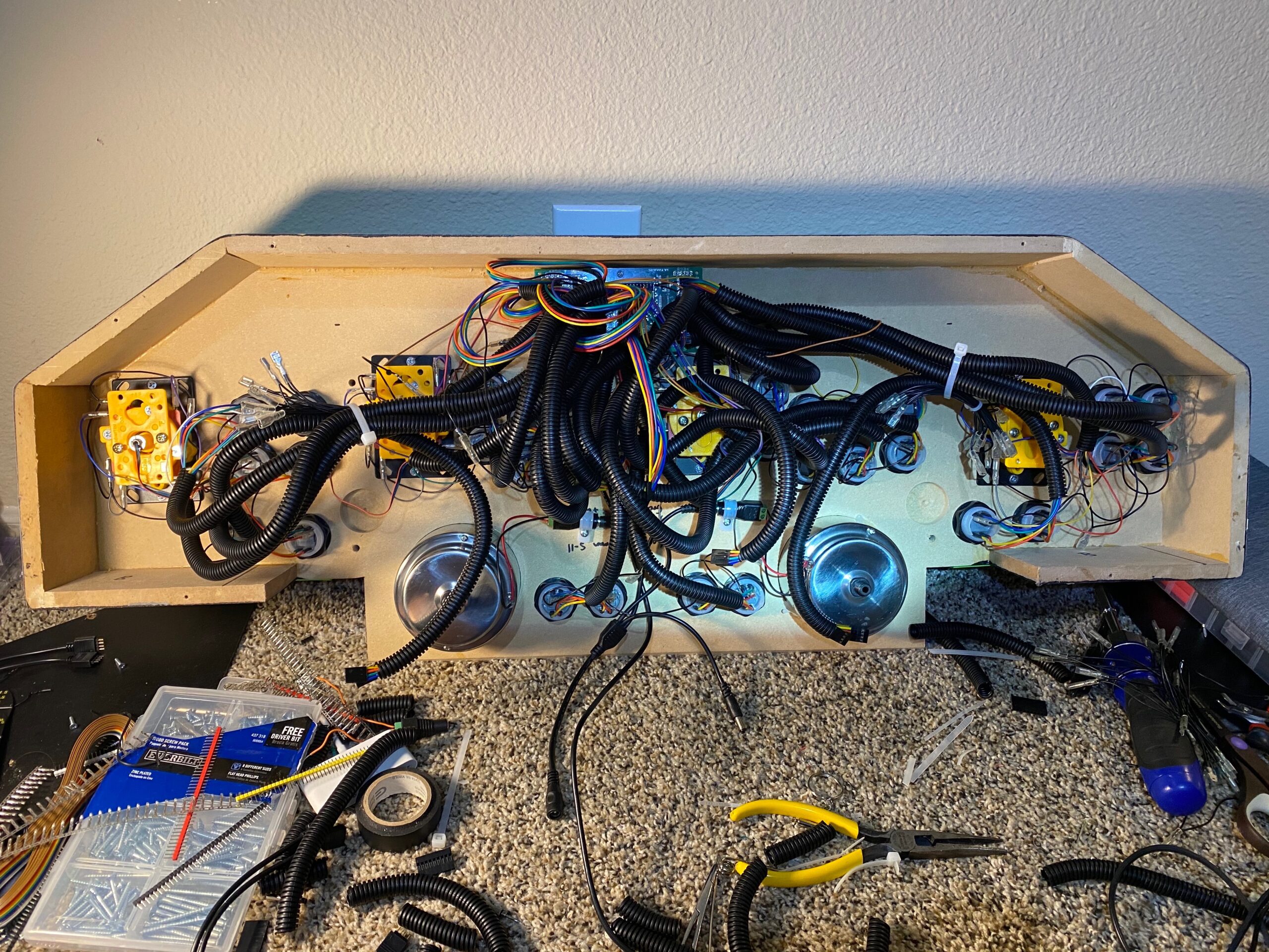
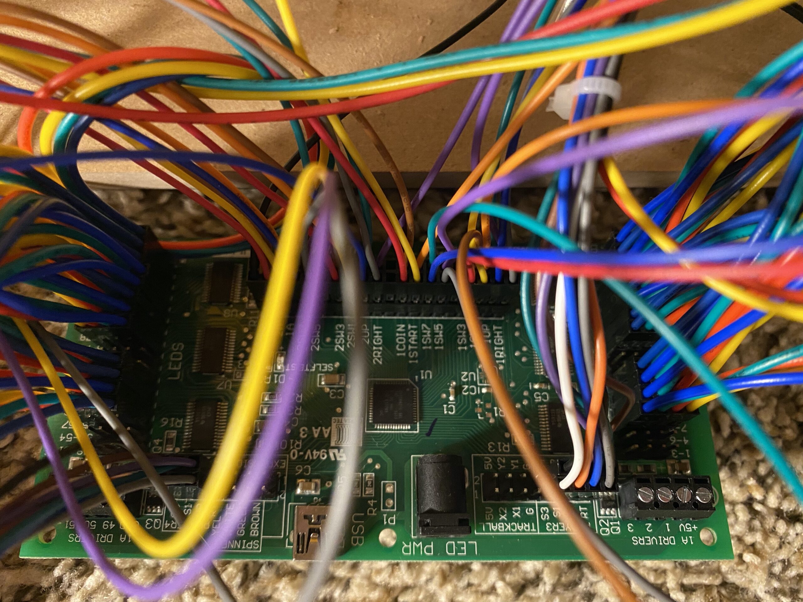
Plug in the RGB LEDs for the joysticks and buttons. Honestly, it doesn’t matter what order you plug them in, because you’re going to have to configure it all at the software level anyways. If you’re an organized person that can work miracles, more power to you for keeping this rat’s nest of wires in order.
Please note: you will have 4 spare pins left over to plug in the merged wires of the Start and Coin buttons for Players 1, 2, 3, and 4.
I found it most easy to take the 3 “standard” ground wires and use 1 for the center, and one for each side. These ground wires are daisy-chained, have a male connector, and the rest of the wire is female connectors. I started from the sides and ran them along the conduit to the center, and then I plugged them into a space connector on each side of the common ground wire for Players 1 & 2.
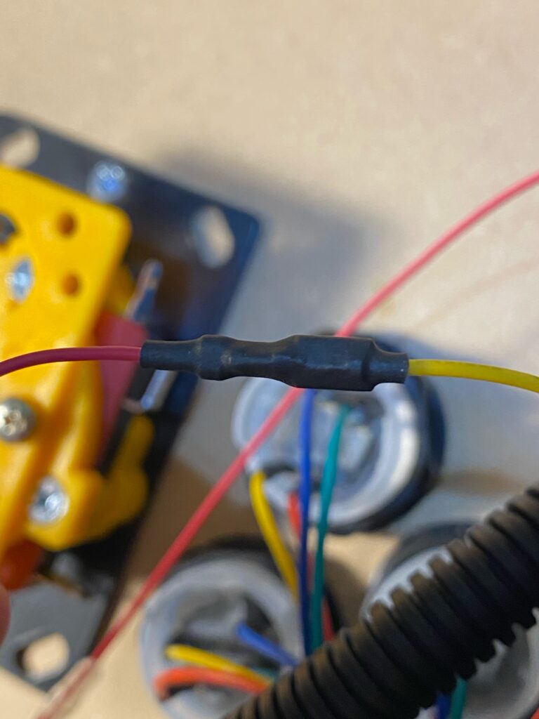
I found it most easy to have unused connectors as a means of slack in the wire, so that I wouldn’t have to bend any of the connectors or the terminals, or put strain on the wires.