Video input
WARNING:
The steps on this page involve frequent contact with Electrostatic-sensitive devices.
Please exercise caution when handling these components.
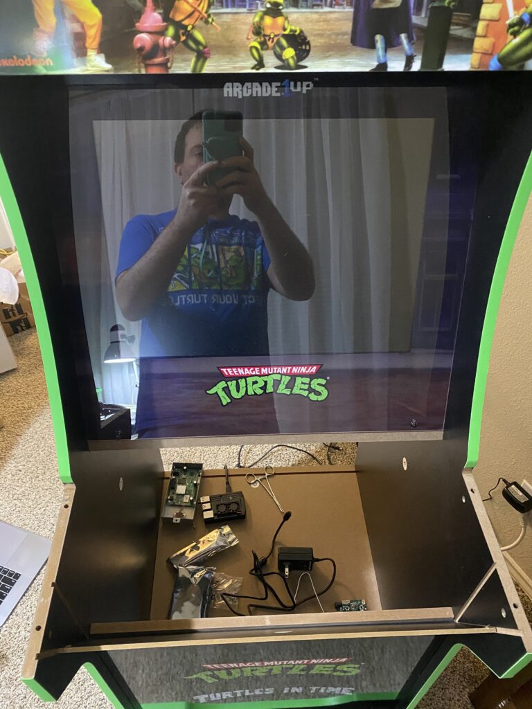
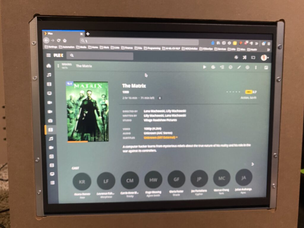
My first step was to get the HDMI switched over to an external device with the driver board, and I simply used my computer and The Matrix to see if it worked — it did, and I was stoked!
My sequence of steps for removing the monitor from an assembled cabinet:
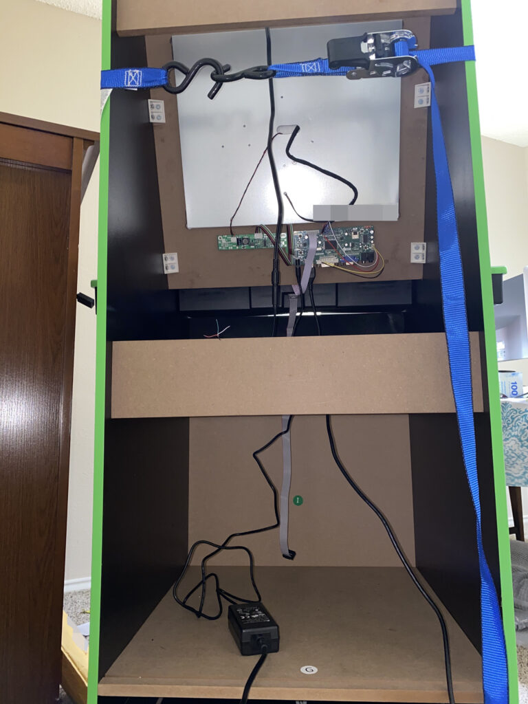
- Remove the back.
- Disconnect the power, speaker, and control deck cables.
- Unscrew the MCU from the monitor enclosure.
- Unplug the LCD inverter cable (red, yellow, and black)
- Unplug the LCD video cable (blue, white, red, and black ribbon). Please take care when doing so by gently rocking back and forth as you lightly pull on the black plastic base, it’s incredibly easy to bend the pins and/or bend the capacitors!
- Remove the control deck (the piece with the 4 joysticks and the buttons).
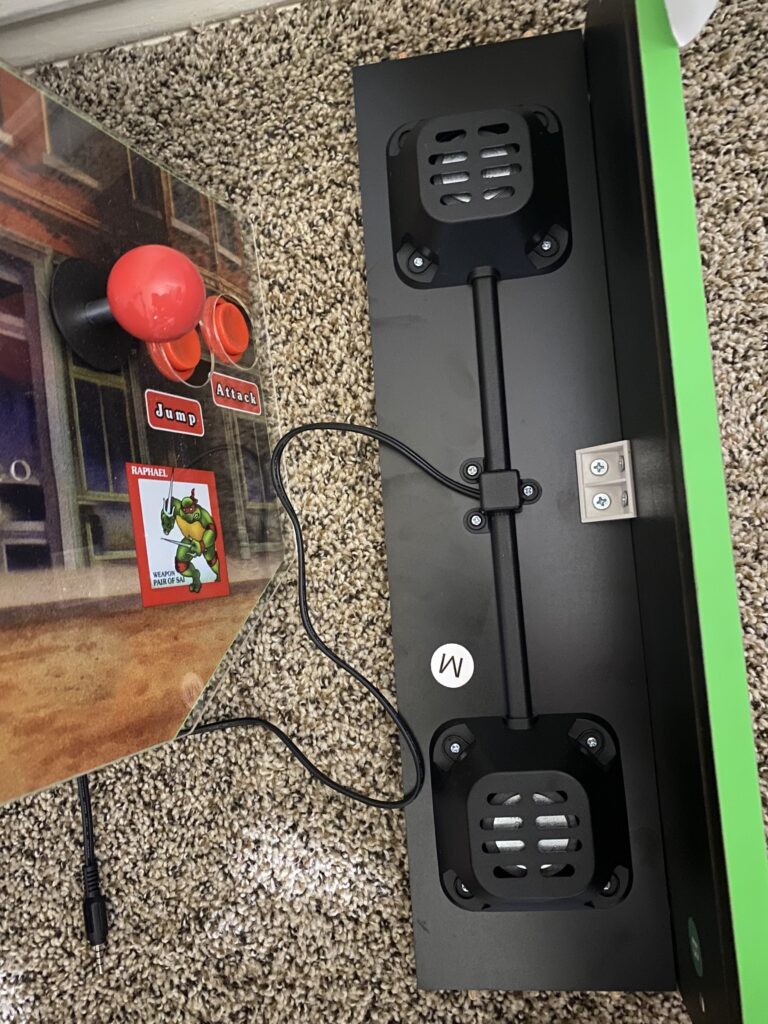
- Remove the L-shaped marquee piece with speakers.
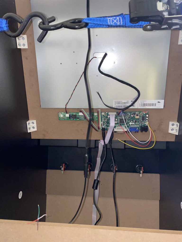
- Cinched a tow strap at the top of the cabinet to hold everything together.
- Unscrew the back brace from one (or both) sides.
- Unscrew the monitor’s brackets from the sidewalls.
- Slowly loosen the tow strap just enough to slide the monitor out — if you have a 2nd person to help you, get them to hold the base as you slide the monitor’s mount out.
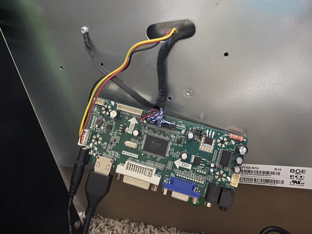
Plugged in the driver board (without replacing any cables just yet — at the time of writing this article, the voltage for the MCU and the LCD driver are the same) for testing HDMI input from my laptop — I wanted to verify that the driver board worked.
Video test works!
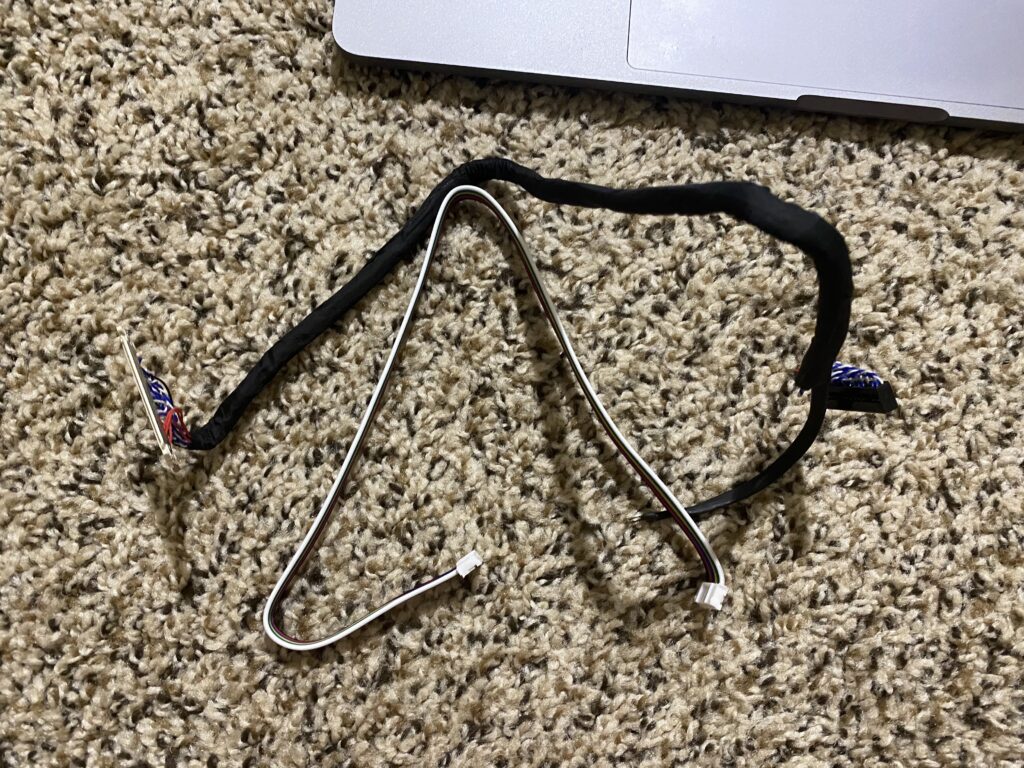
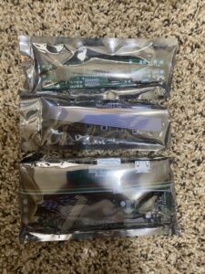
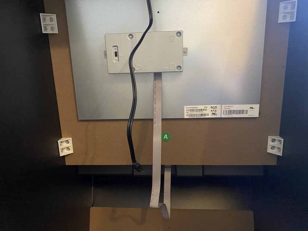
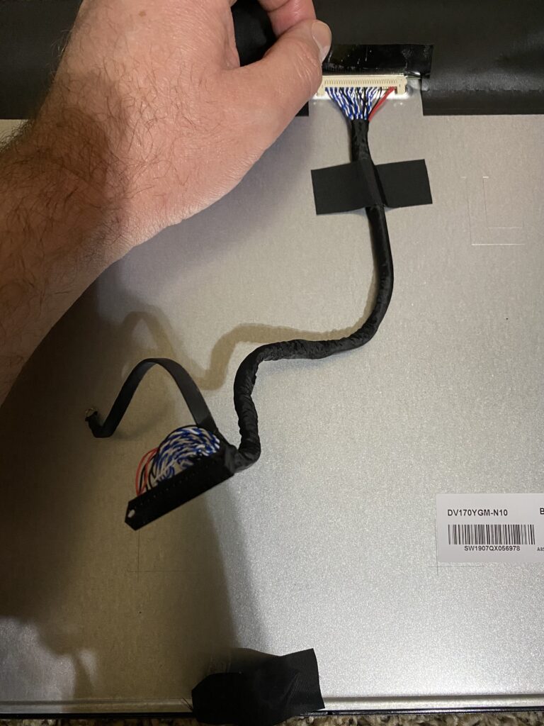
Remove the new LCD cables from the display kit that you ordered from the Bill of Materials page.
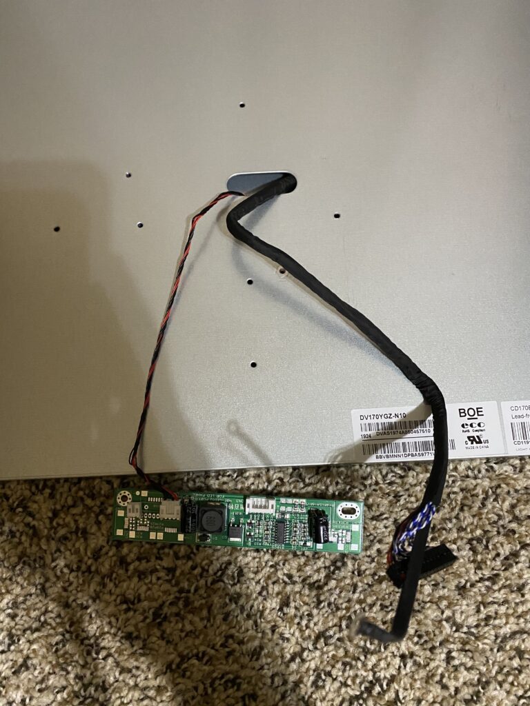
I then had to disassemble the monitor mount (wood) and its enclosure (metal). There are multiple screws on both sides that connect the enclosure to the mount, which you will need to remove. Then, unscrew the ground wire, push a little bit of slack for the inverter and video cables through, and unscrew the monitor from the enclosure. Inside, you’ll find the inverter PCB.
You should be able to slowly fold open the monitor and enclosure like a book, and pull the remaining slack of the inverter and display cords through. The display cord will be taped down to the back of the monitor, and the inverter PCB and its cord will be taped down to the enclosure.
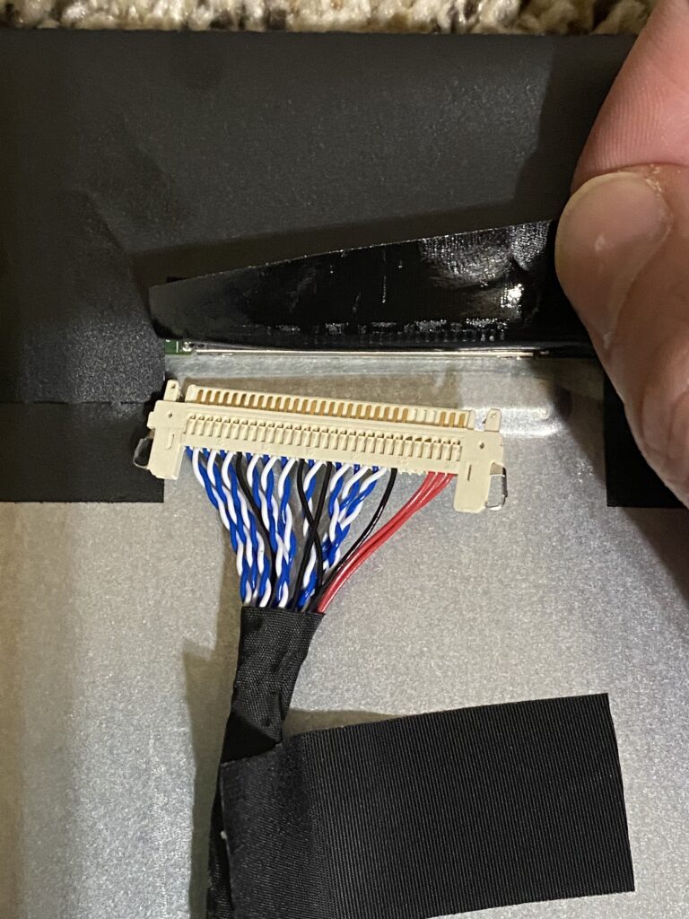
Peel the tape off of the monitor just enough to slide the cord out from under it, but take care in doing so, since you’re going to reuse it to hold the longer, replacement cord. Then, peel the tape back from the connector, and disconnect the display cord by lightly pushing on the metal pins on the side and easing the display ribbon off of the monitor’s connectors.
Please note that the red wires and 3 separate pins are on the right-hand side.
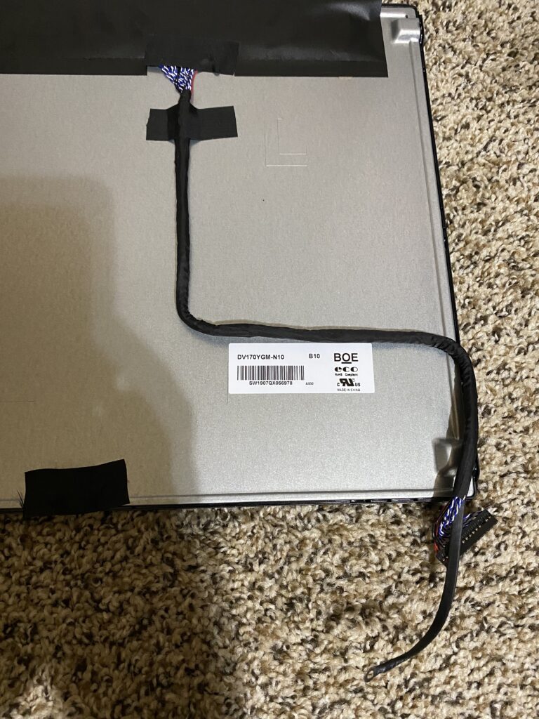
Tape the longer replacement cord (that came with the kit) down to the monitor.
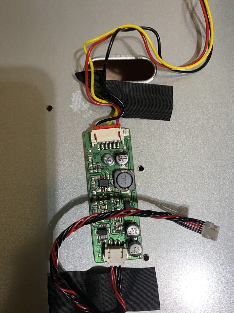
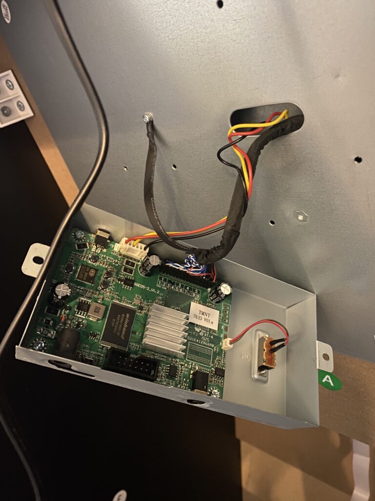
Disconnect and remove the stock inverter board.
You’ll notice that the video and inverter cords are long enough to reach out of the enclosure and provide slack for you to work with.
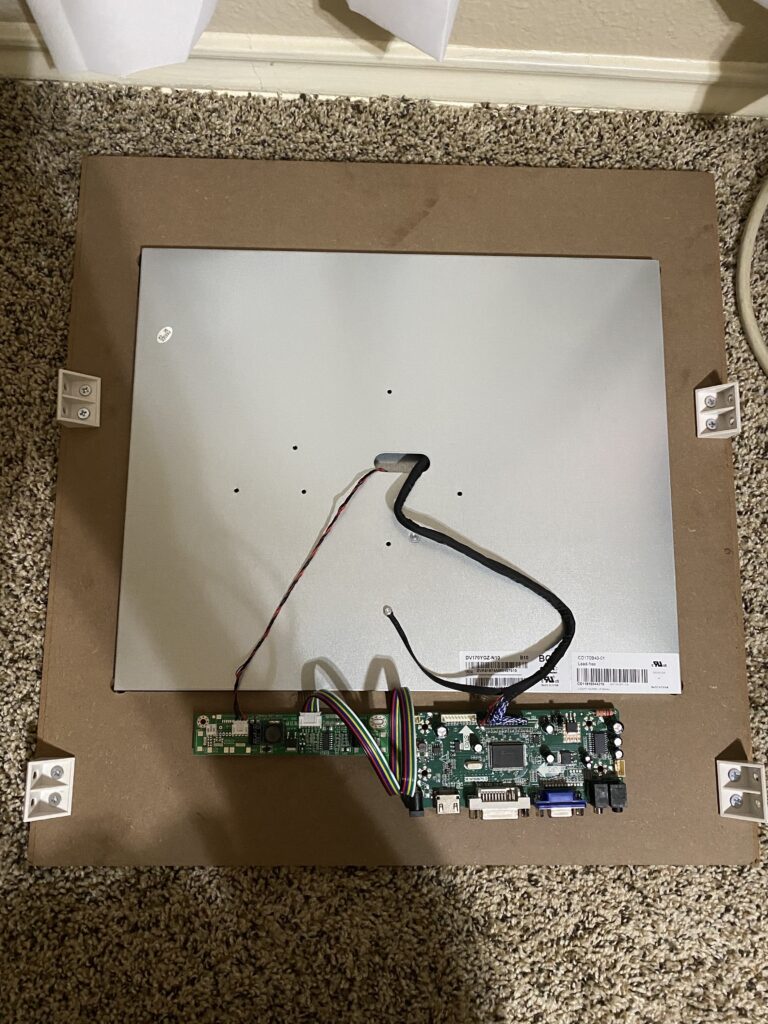
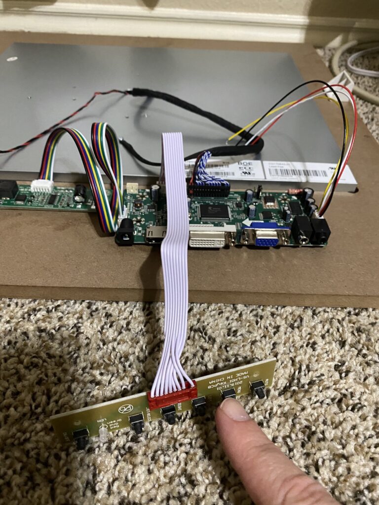
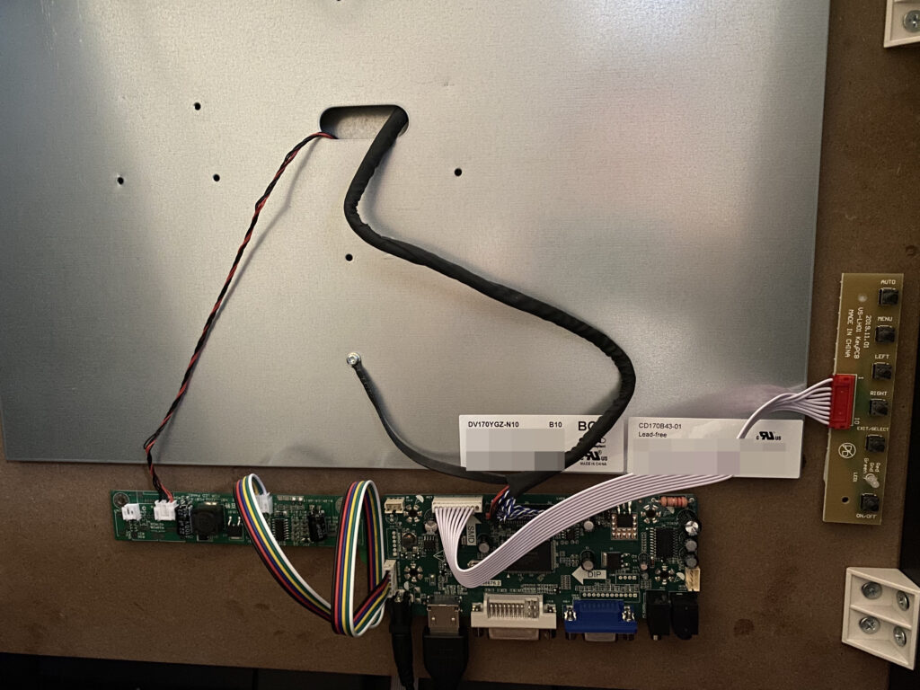
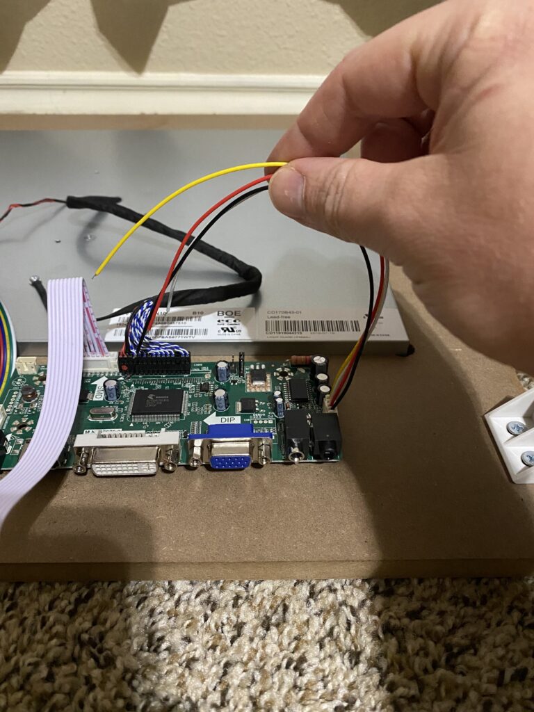
- Mount the 3 boards to the wooden monitor mount (do not attach any of these to the metal enclosure!) with the double-sided 3M tape that you ordered from the Bill of Materials page.
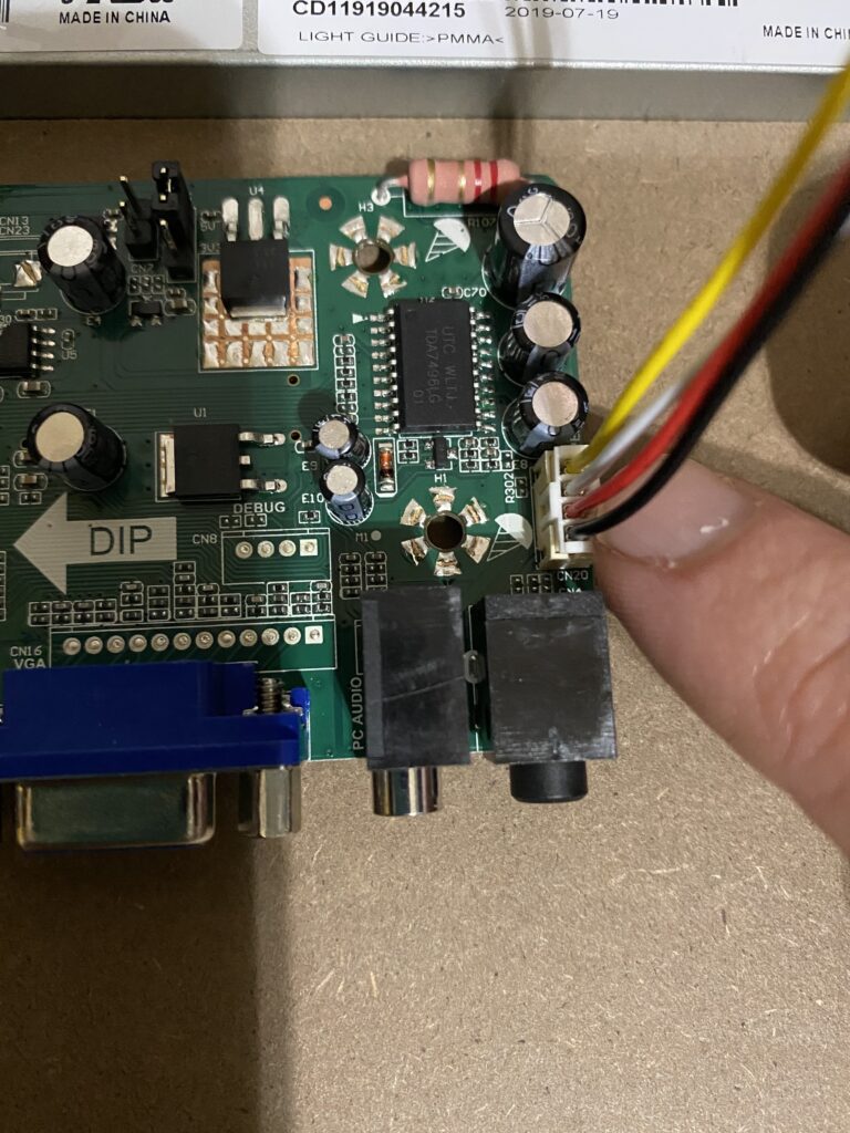
- Inverter — red and black power supply cable to the LCD monitor.
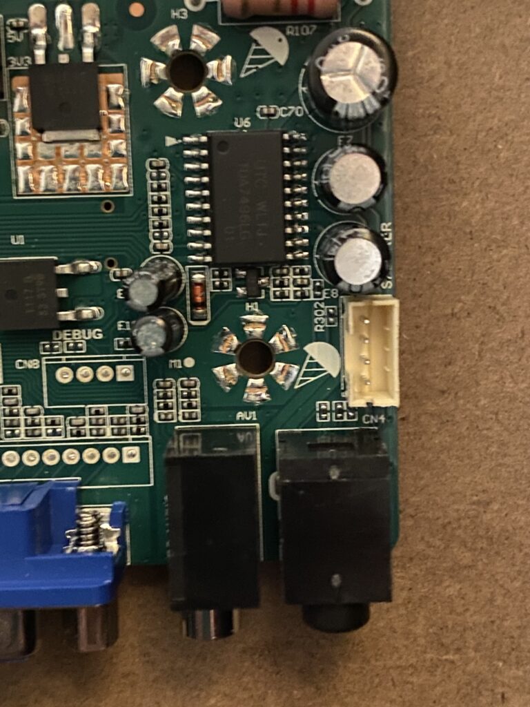
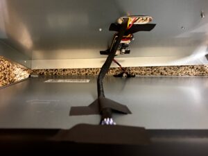
- Driver — HDMI, DVI, and VGA input alongside of other terminals.
- Daughter — board with multiple buttons for controlling the monitor and adjusting the speaker volume.
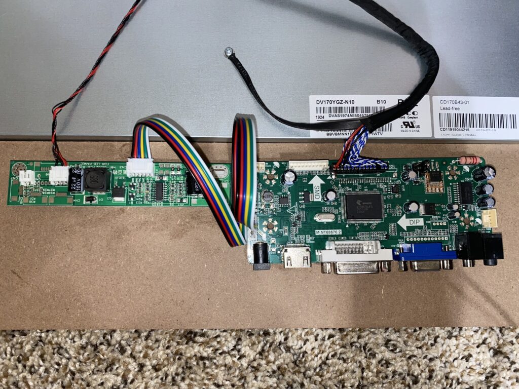
- Attach the ground from the new video cable to the metal enclosure where the old one was connected.
- Connect the video cord to the driver board.
Please note: when plugging the new video cable from the monitor into the driver board, the red side of the ribbon goes on the left. - Connect the inverter cord to the inverter board.
- Connect the inverter board to the driver board — I looped the cable to reduce the slack.
- Attach the daughter board to the driver board.
- Remount the monitor into the cabinet (you should get a 2nd person to help you, unless you disassemble this further and piece it back together based on the manufacturer’s installation instructions.)