Audio output
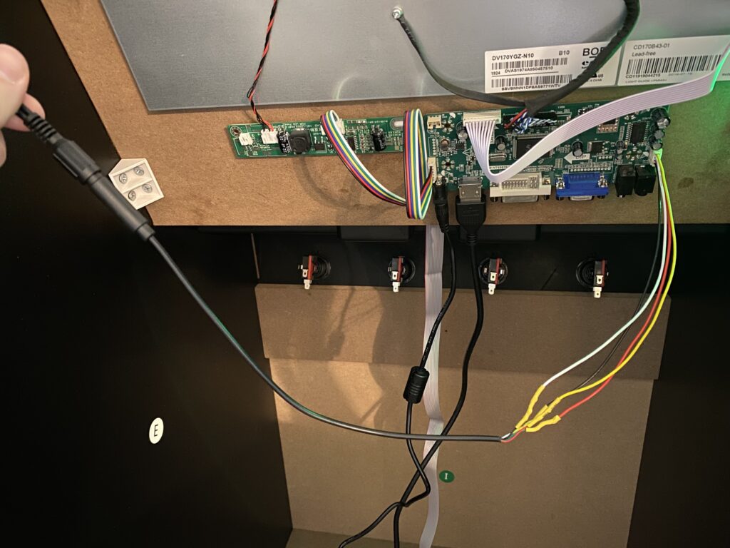
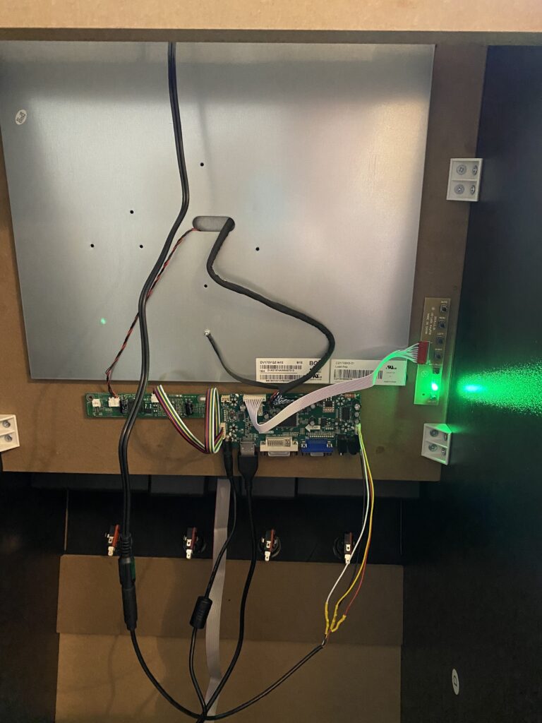
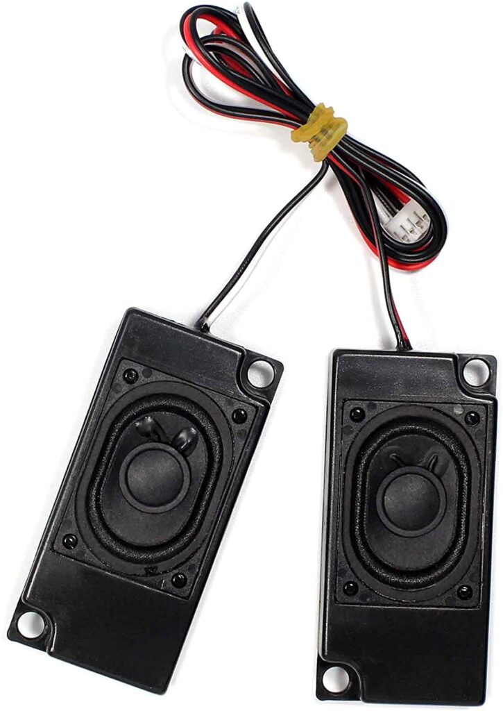
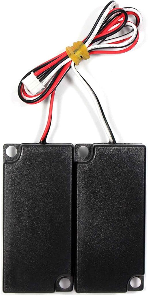
Please allow me to start with the results and work my way backwards. This is video and stereo audio with the stock monitor and stock speakers and no external amplifier (well, the driver board is the amplifier, but most modders seem to use this amplifier — which we’re going to skip). I was lucky to have found and followed this video that MatrixPrime made, which was based on instructions that he had found on Reddit (I couldn’t find the thread that he was referring to).
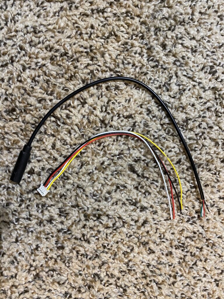
Using the JST and 3.5mm headphone jack from the Bill of Materials page, we’ll connect the colors of each piece together using the table below.
Adapter connections:
| JST | Headphone | Channel | Polarity |
|---|---|---|---|
| Yellow | Red | Left | Power |
| White | Black | Left | Ground |
| Red | Green | Right | Ground |
| Black | White | Right | Power |
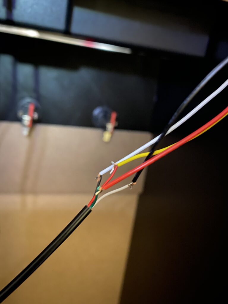
First, I tested the speakers by simply twisting the wires together. It worked as expected, so then I began on creating the permanent implementation.
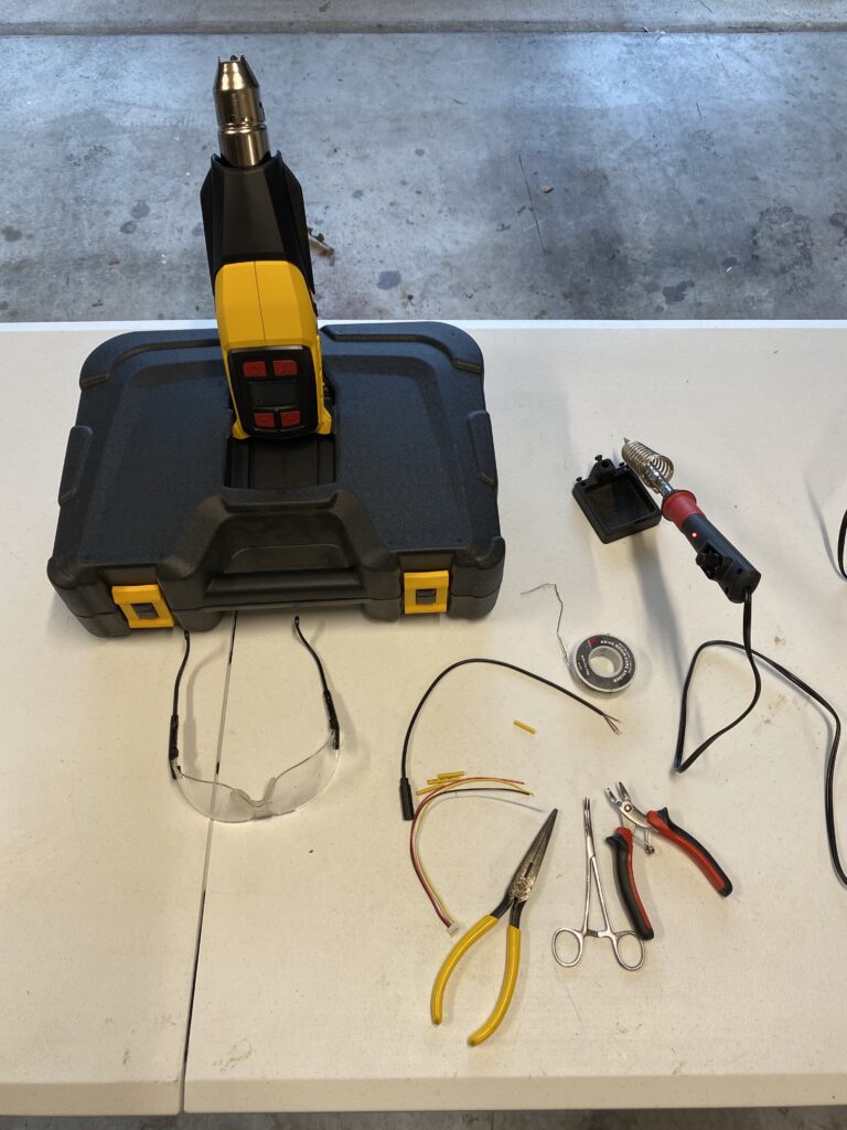
I tend to solder outside due to the fumes, and prepared my environment by heating up the soldering iron.
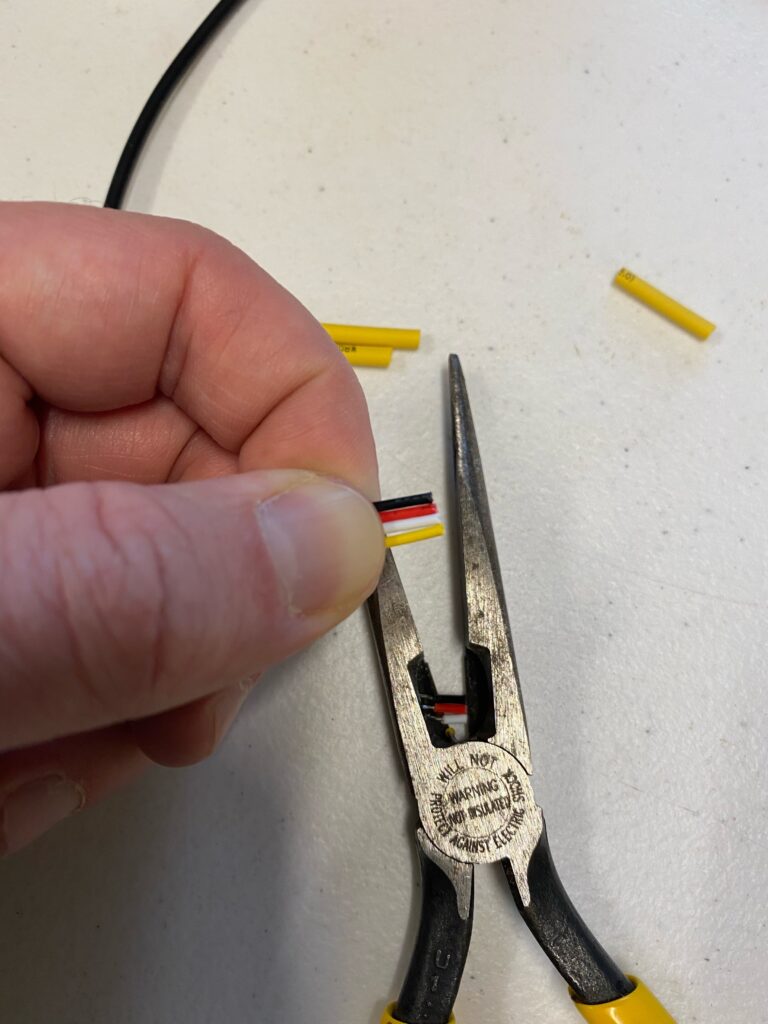
- Trim the JST cables.
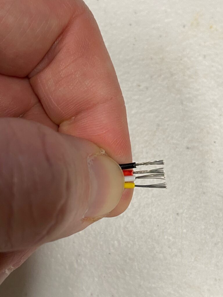
- Strip each of the cable tips.
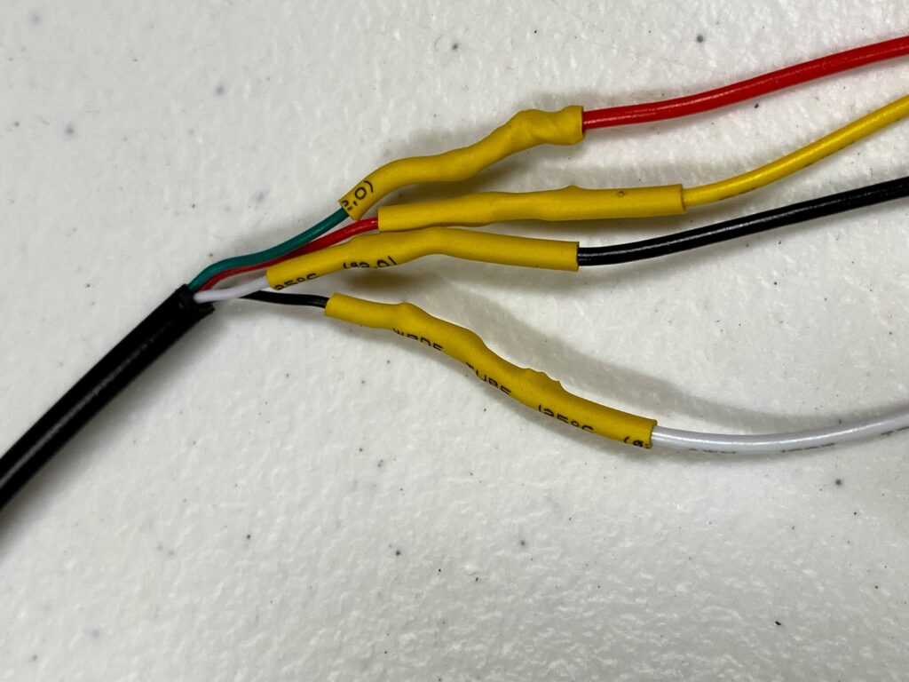
- Since I use heat-shrink tubes that reduce to half of their size, I select the smallest possible diameter to slide over the cable.
- Use 1 heat-shrink tube for 2 cables by cutting it in half. Thus, 2 tubes will cover 4 cables.
- Slide each of the 4 heat-shrink tubes onto their reciprocal JST cable.
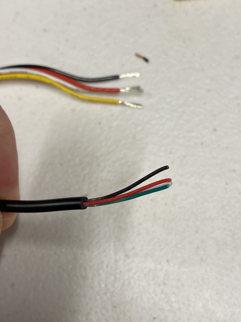
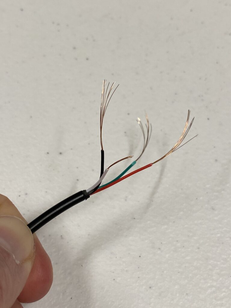
- Trim the 3.5mm female jack cables.
- Strip each of the cable tips.
Please note: these audio cables are very brittle, which is why I used a micro cutter on these instead of pliers.
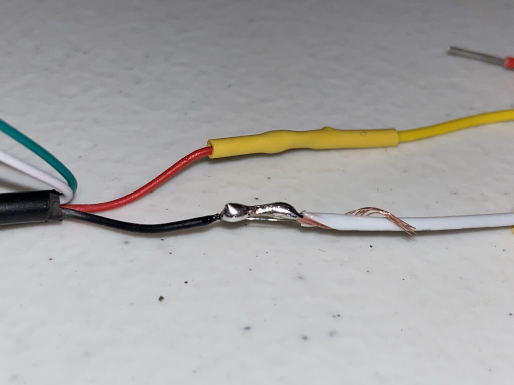
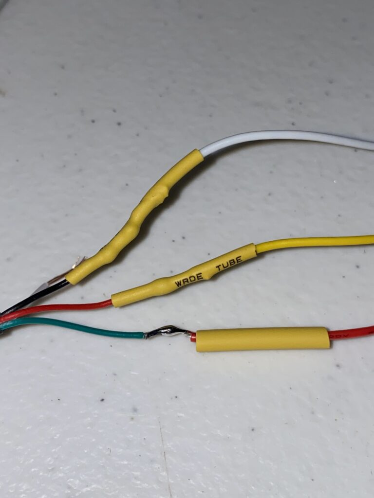
- Following the table above, match the cables to each other.
- Wrap each reciprocal cable around each other
- Solder the cables where they overlap with each other — you’ll have leftover cable on the side, and will use the Micro Cutter to trim back to the soldered point.
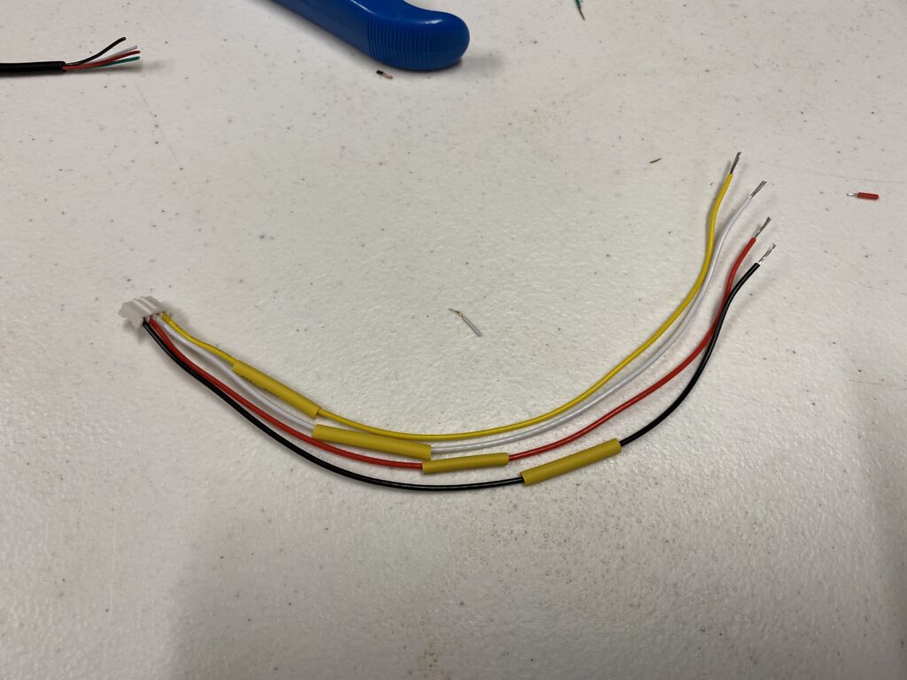
- Slide the heat-shrink tube over the soldered point, and try to evenly cover the two cables.
- Heat up the tube to shrink it, and then repeat this entire process 3 more times to complete the audio cable.
Now, your cable is complete!
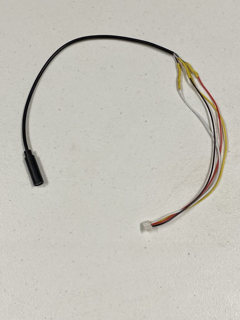
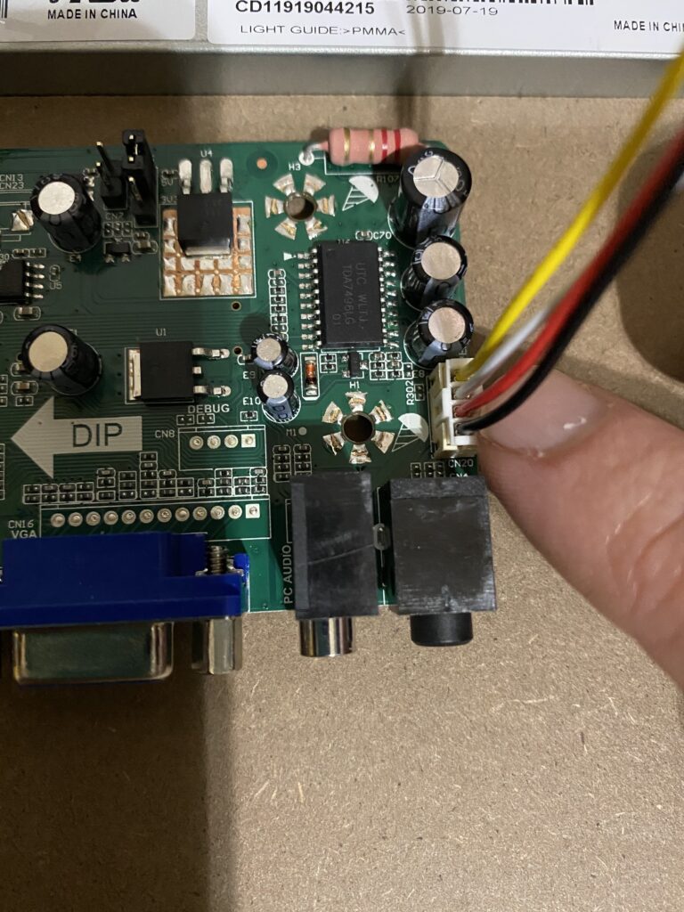
Plug in your newly created cable, and test it.