
Coin insert interrupts
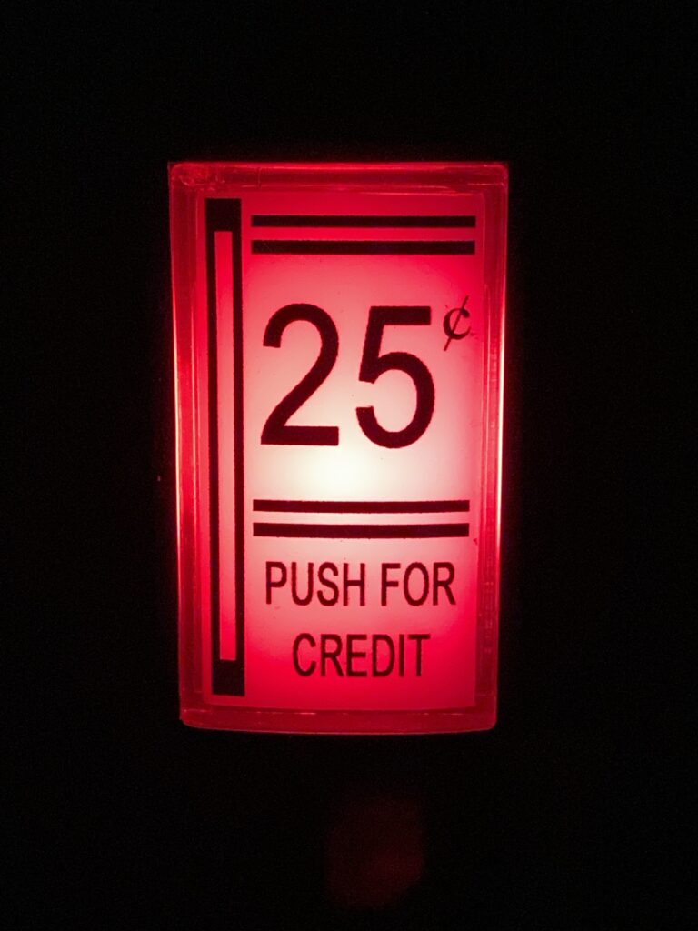
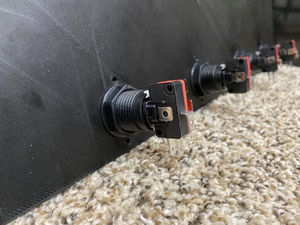
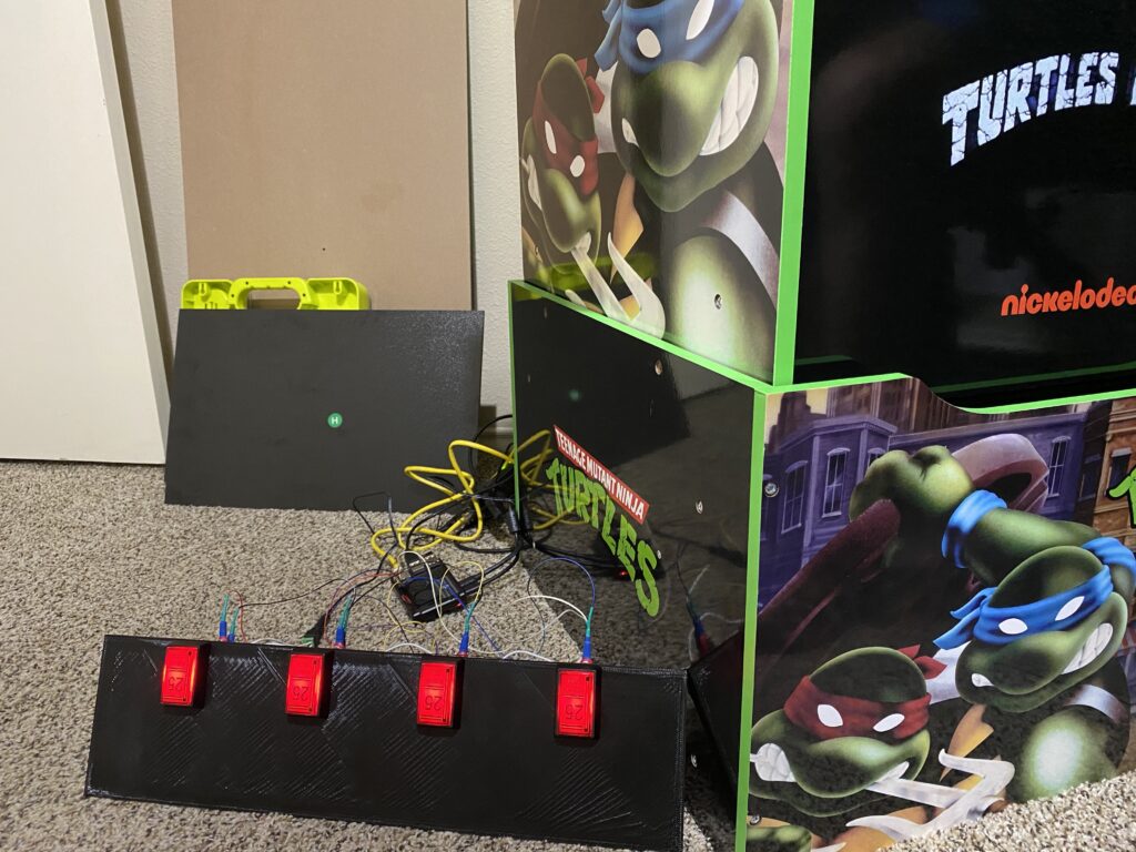
I was going to install illuminated coin doors but I couldn’t find an economical quadruple slot model, or coin acceptors but I didn’t want to add onto my workload for fabricating a door with hinges and a reciprocal collection bin. For the sake of expedited progress, I decided to use illuminated coin push buttons instead. The use of these buttons mounted to a plastic piece that I designed and 3-D printed provides a nostalgic feeling without the need for damaging the stock cabinet (specifically, the “I” or “J” pieces) while also freeing up primary control buttons due to the USB encoder’s maximum inputs limited to 48 (using my technique and at the time of this writing, I have 52 inputs).
DIY Solar Power with Will Prowse
If you want to refresh your memory about electricity, check out this excellent video by Will Prowse, with notable points at:
- Volts/Amps Introduction: 3:15
- Voltage: 3:35
- Amperage: 4:30
- Watts: 5:57
- Parallel and Series Connections: 12:51
- How to Size a Fuse and Wire: 18:49
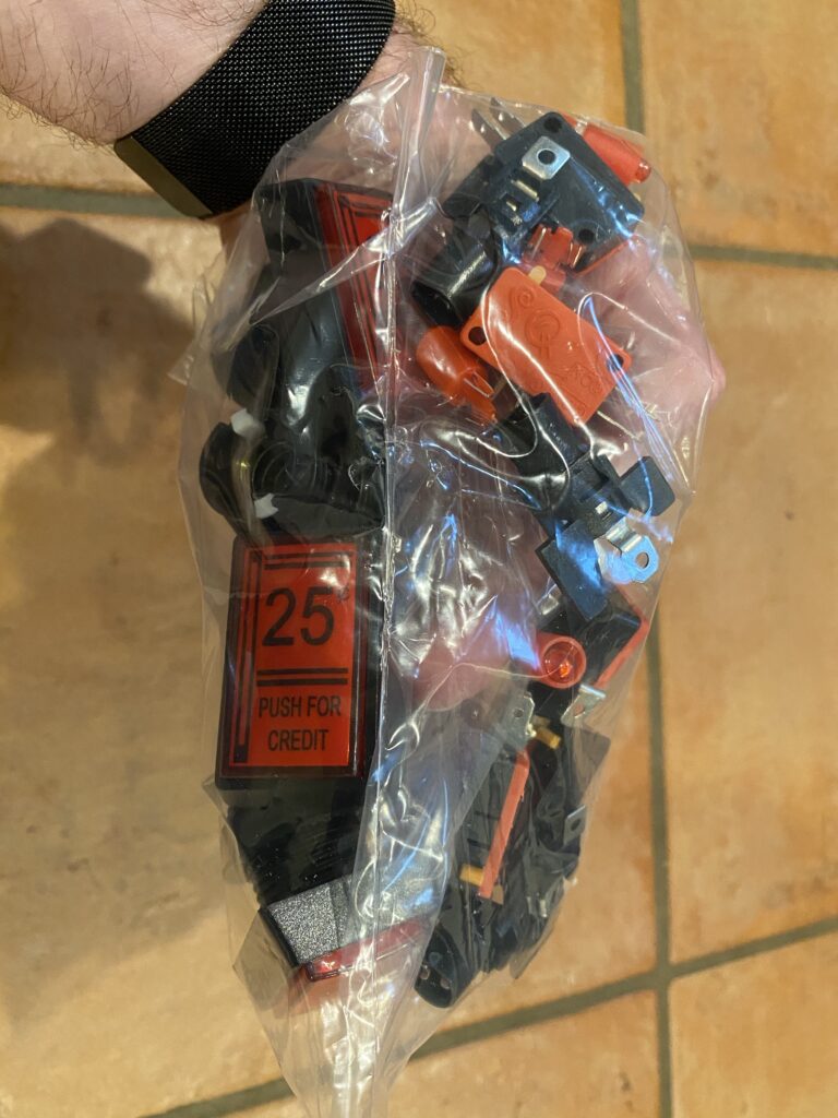
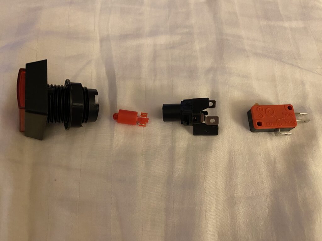
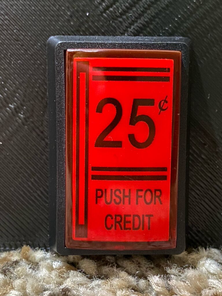
- Open the bag and count the parts to make sure that you received a full order — there are 5 parts per unit:
- Button with protruding bolt.
- Mounting nut.
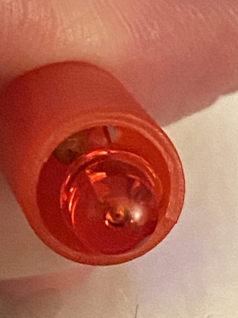
- LED with inline resistor.
- 12 volt LED harness
- Micro-switch
- The 12V harness rotates to lock/unlock the LED behind the button. Initially, it was a little difficult to disassemble everything, which I would assume is from temperature fluctuations in transit.
Since I needed to create a power cord for running the LED lights on these coin buttons, a few questions had to be answered for calculating what kind of wire to use:
| Voltage (Direct Current) | 12 |
| Current (Amperes) | (Answered below) |
| Length (Meters) | (Answered below) |
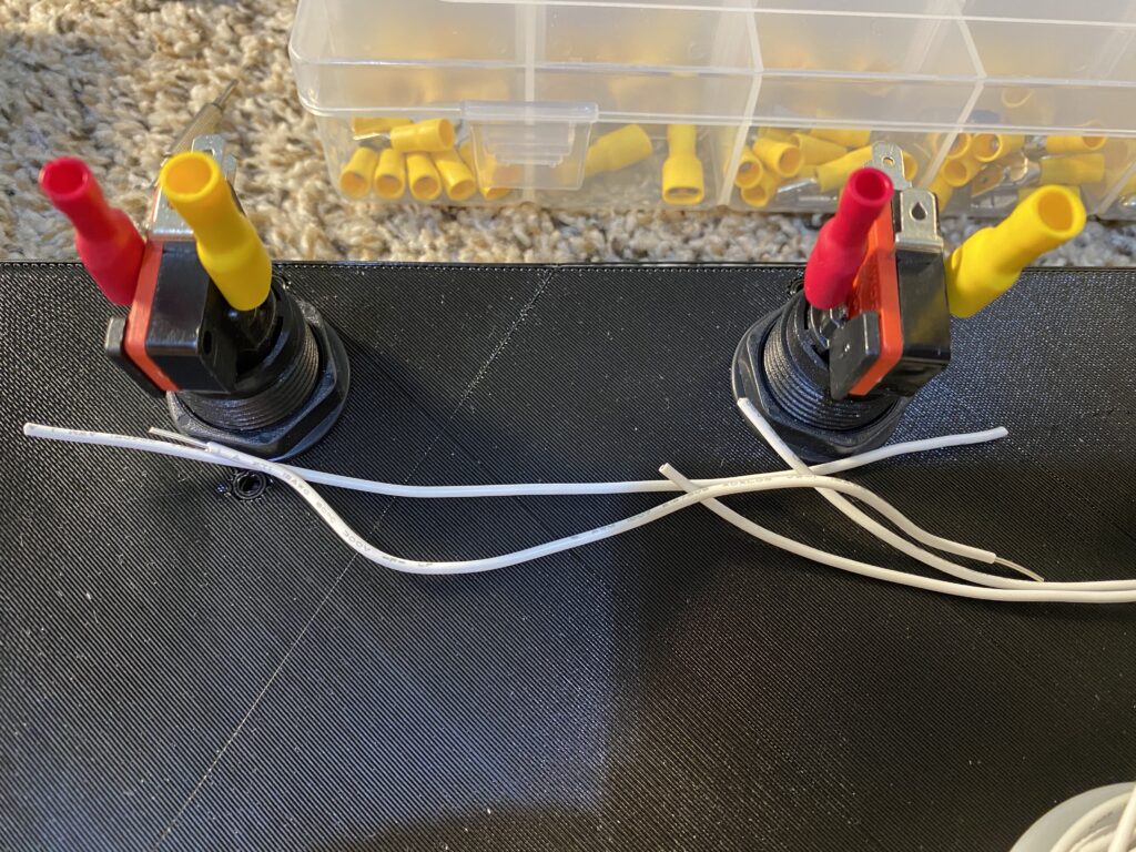
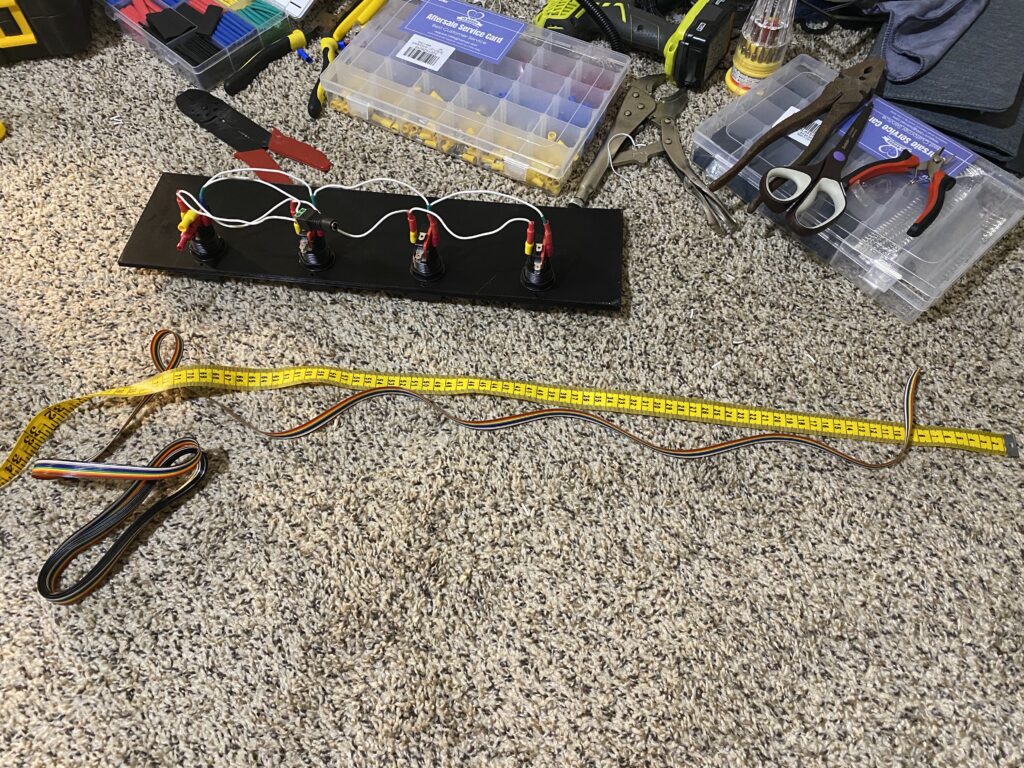
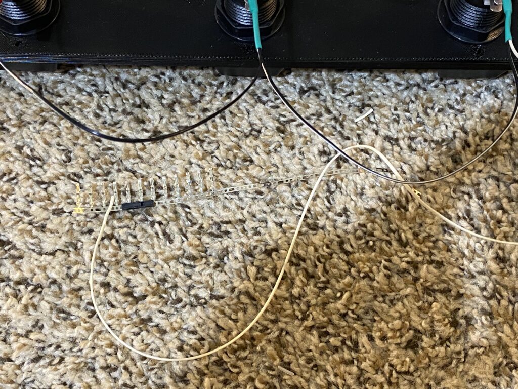
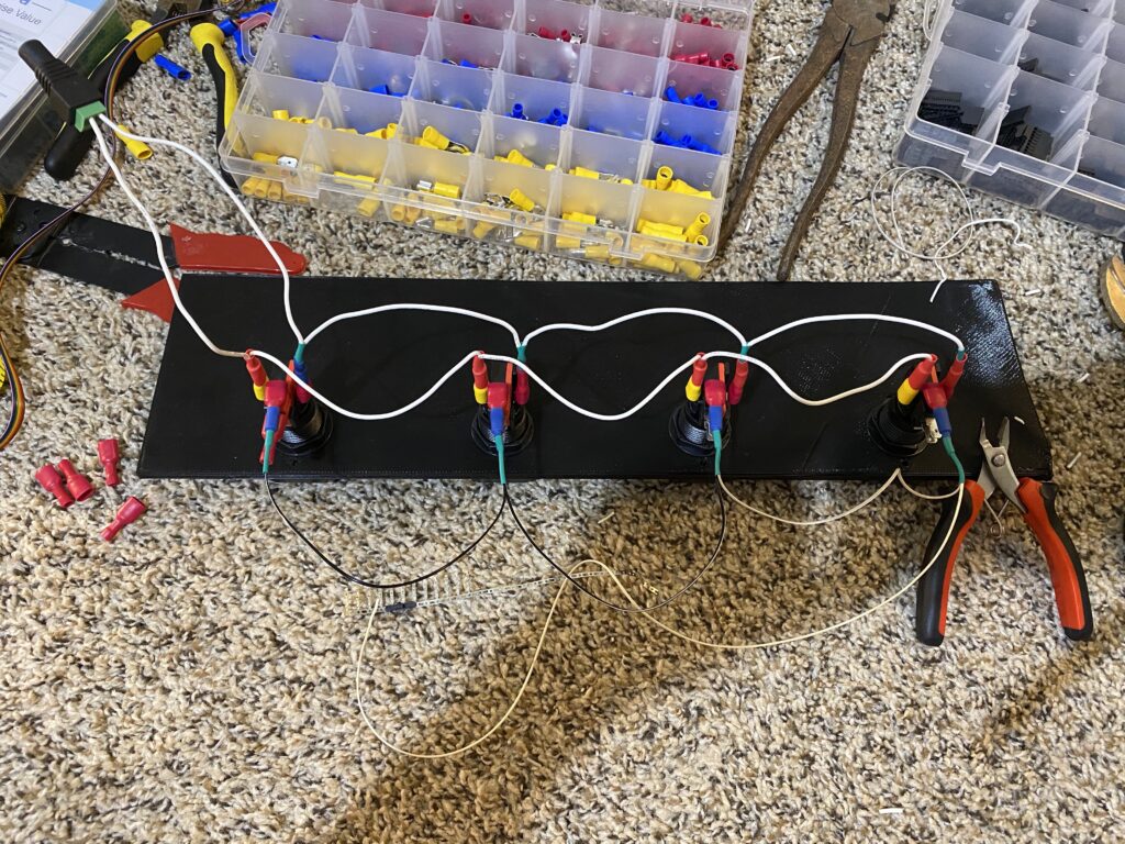
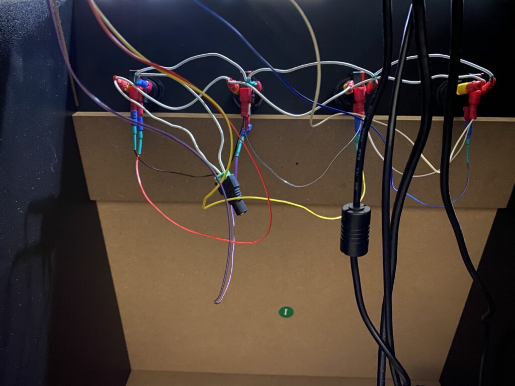
I made this circuit parallel instead of series, so that if one button experiences issues, everything else continues running. This also makes it easier to trace (e.g. a burned out light bulb) than having to try and individually trace every button each time that a LED burns out or there’s a connectivity problem. The distance between each of the button connectors is approximately 10 Centimeters, with 15 Centimeters being the minimum length that I would use in order to have enough slack for connectors. I opted for 20 Centimeters (0.2 Meters — this is the number that you’ll see used in calculations below) between each button, as well as for the female adapter that receives the power so that I have a little more leeway.
| Voltage (Direct Current) | 12 |
| Current (Amperes) | (Answered below) |
| Length (Meters) | 0.2 (20 Centimeters) |
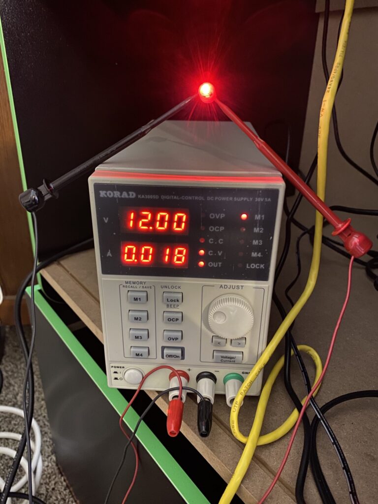
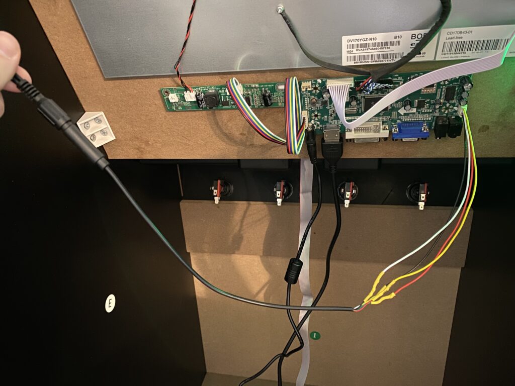
The illuminated cup holders on the new control deck use 12 Volts and have an extra plug available on the splitter, so I was able to tie these illuminated coin buttons into the same circuit. The product description for the coin buttons only listed 12 Volts, but didn’t list the current draw of the LED, so I had to work my way backwards. I had my bench power supply by my desk (but you could also use a multimeter), so I set it to 12 Volts and 1 Ampere to match the power supply of the transformer that came with the control deck (for its cup holders), and measured the draw of the spare bulb, all coin buttons lit up, and all coin buttons plus cup holders powered on.
| Device | Current (mA) | Current Peak — 125% of mA |
|---|---|---|
| Single coin button LED | 18 | 22.5 |
| 4 coin button LEDs | 83 | 104 |
| 2 cupholder LEDs | 3 | 3.75 |
| 4 Coin + 2 Cup | 91 | 114 |
Our range is 91 – 114 Milliamperes (0.91 – 0.114 Amperes), so we’ll use 0.114 Amperes for our upcoming calculations.
| Voltage (Direct Current) | 12 |
| Amperage (Amperes) | 0.114 (114 Milliamperes) |
| Length (Meters) | 0.2 (20 Centimeters) |
The simple way to solve this is with a simple Python script that I wrote, Simple Electrical Calculator, which is still rough around the edges. Below, I’ll cover some of the formulas to use for figuring out the rest of our needs.
Since we know the Voltage is 12 and our current is 0.114, then we’ll calculate the resistance R in Ohms (Ω) using Ohm’s law for circuit analysis:
R=\frac{ V }{ I }R=\frac{ 12 }{ 0.114 }Ω = 105.26
Related to Ohm’s law and for the sake of demonstrating a concept, let’s calculate the power P in Watts (P) with respect to electromagnetism using a Volt-ampere:
P = V \cdot I
P = 12\ Volts \cdot 0.114\ Amps
Wattage = 1.37
The maximum amount of Power that we can draw from the plug is 12:
P = 12\ Volts \cdot 1\ Amp
So, we’re well within capacity:
12\ Capacity\ -\ 1.37\ Consumed\ =\ 10.63\ Available
Let’s update our table:
| Voltage | 12 |
| Amperage | 0.114 |
| Length | 0.2 |
| Resistance (Ohms) | 105.26 Ω |
| Wattage | 1.37 |
This article and my related Python script, Simple Electrical Calculator, are a work in progress. In order to give the most accurate results, let’s make use of Solar Wind‘s calculation table and formula:
| E.U. Size | Max current (Amps) | A.W.G. |
|---|---|---|
| 0 | 0 | Too small |
| 0.5 | 5 | 20 |
| 1.5 | 11 | 16 |
| 2.5 | 17 | 14 |
| 4 | 41 | 12 |
| 6 | 53 | 10 |
| 10 | 73 | 8 |
| 16 | 99 | 6 |
| 25 | 131 | 4 |
| 35 | 192 | 2 |
| 50 | 240 | 1 |
| 70 | 297 | 2/0 |
| 95 | 354 | 3/0 |
| 120 | 414 | 4/0 |
| 150 | 476 | 300MCM |
| 185 | 540 | 350MCM |
| 240 | 645 | 500MCM |
| 300 | 741 | 600MCM |
| 400 | 885 | 750MCM |
| 500 | 1025 | 1000MCM |
| 630 | 1190 | Unknown |
| -1 | -1 | Too large |
round(\ \frac{ Amps \cdot Length \cdot 0.04 }{ Volts \cdot Loss\ /\ 100 } \cdot 100\ )\ /\ 100Let’s plug our values in:
- Current = 0.114 Amperes
- Length = 0.2 Meters
- Pressure = 12 Volts DC
- Loss = 3%
round(\ \frac{ 0.114 \cdot 0.2 \cdot 0.04 }{ 12 \cdot 3\ /\ 100 } \cdot 100\ )\ /\ 100 =0.25333\ /\ 100 = 0.00253
Matching this value in the range on the table for E.U. Size, you’ll see that 0.00253 is between 0 and 0.5. So, 20 A.W.G. is our answer.
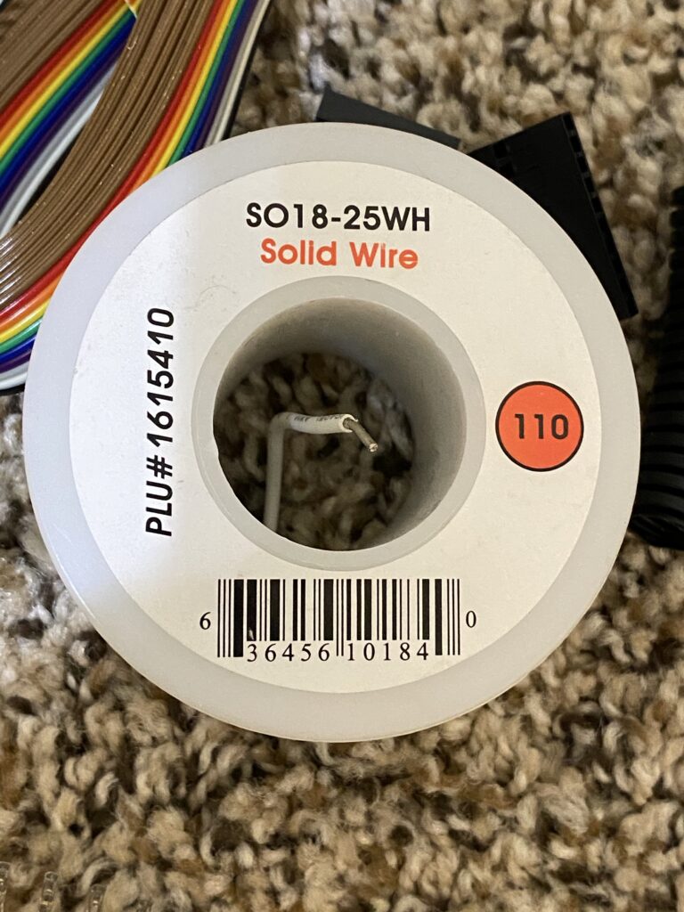
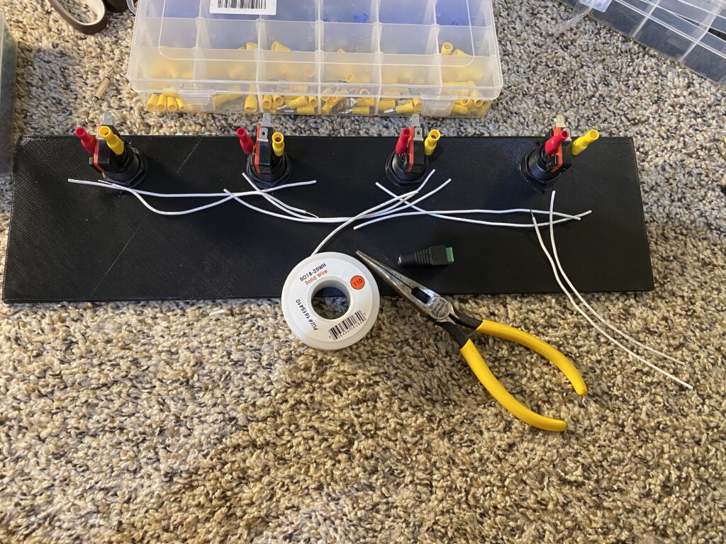
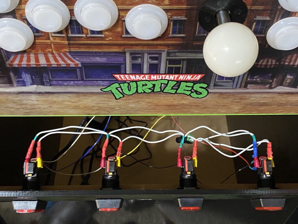
- For the 12V LED wiring, I went with what I had on hand, and is slightly thicker than our requirements: 18 AWG.
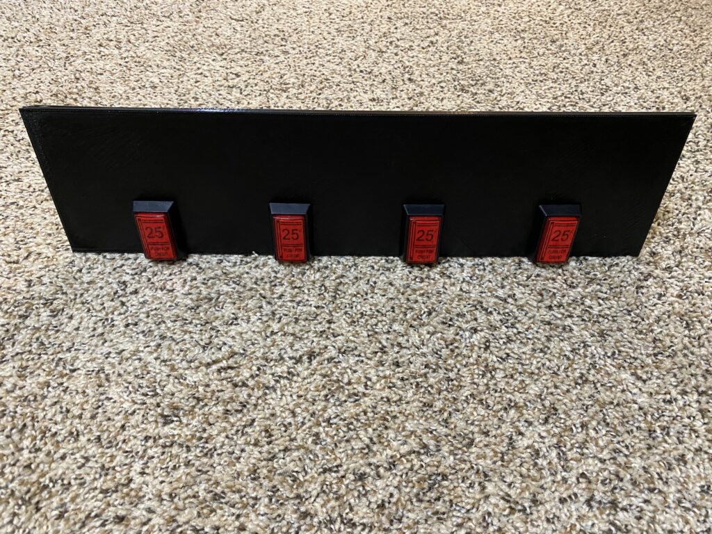
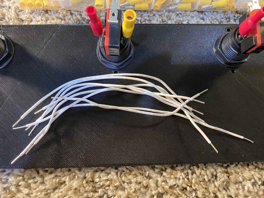
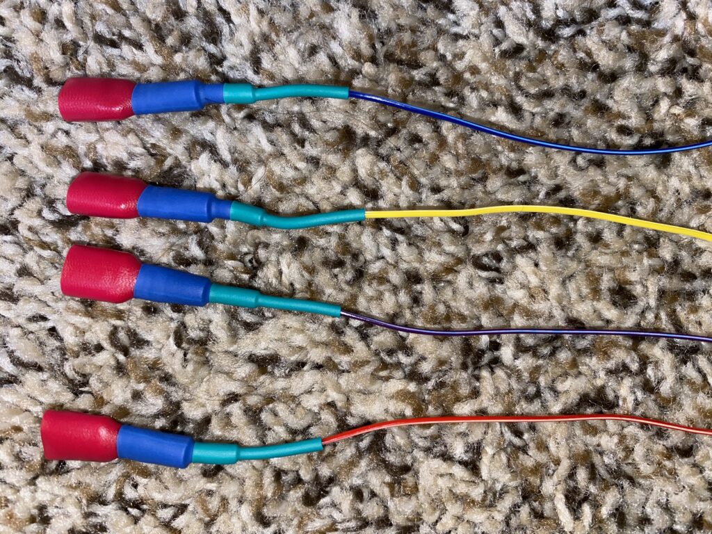
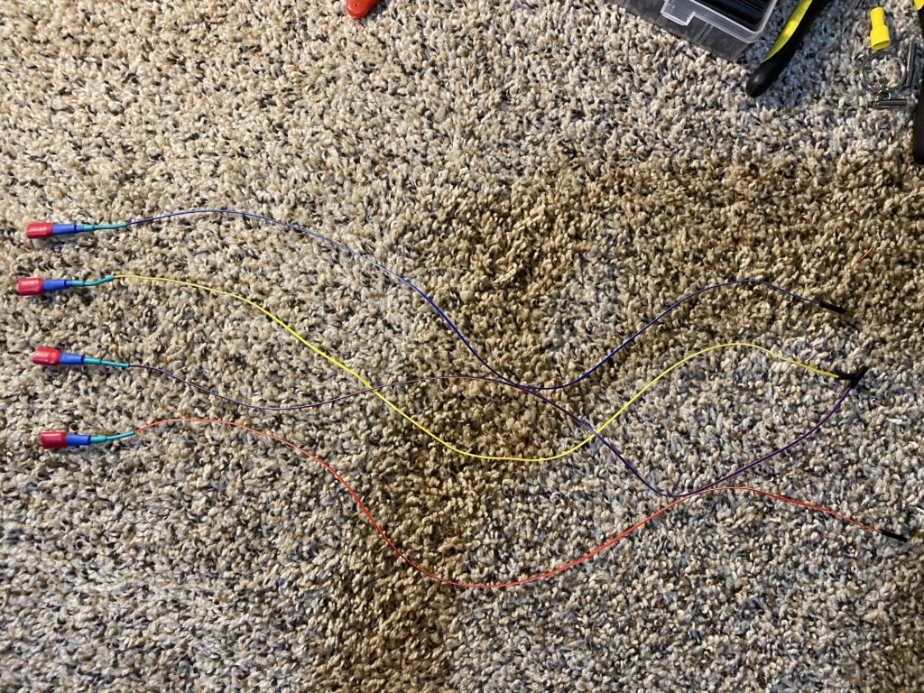
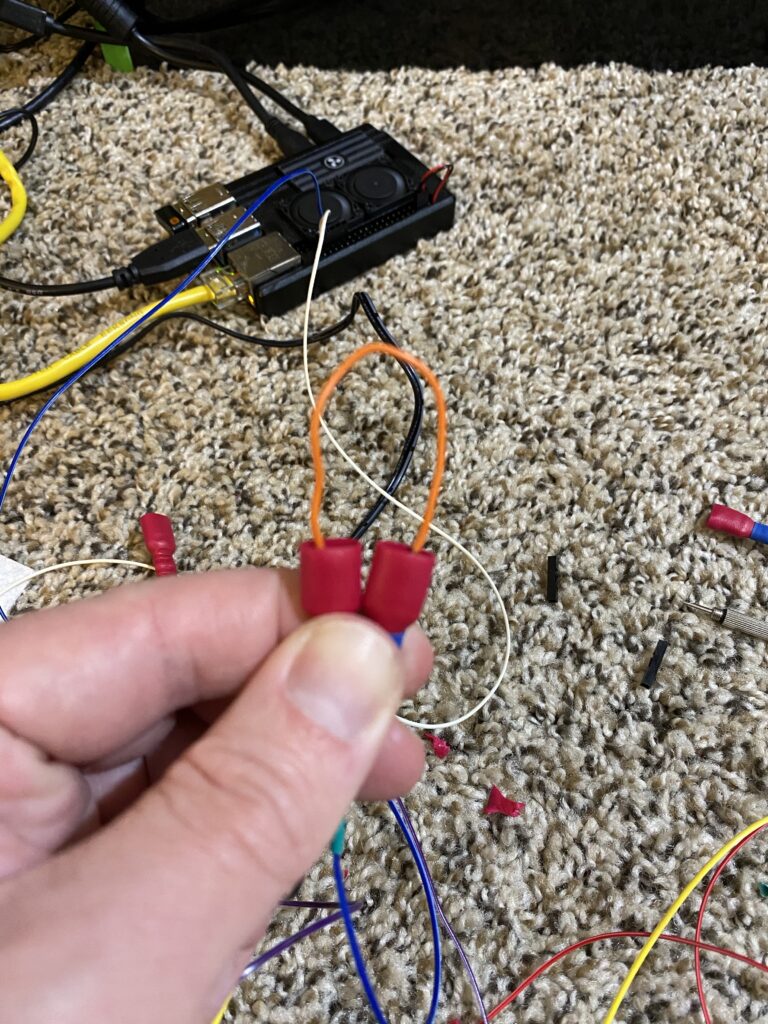
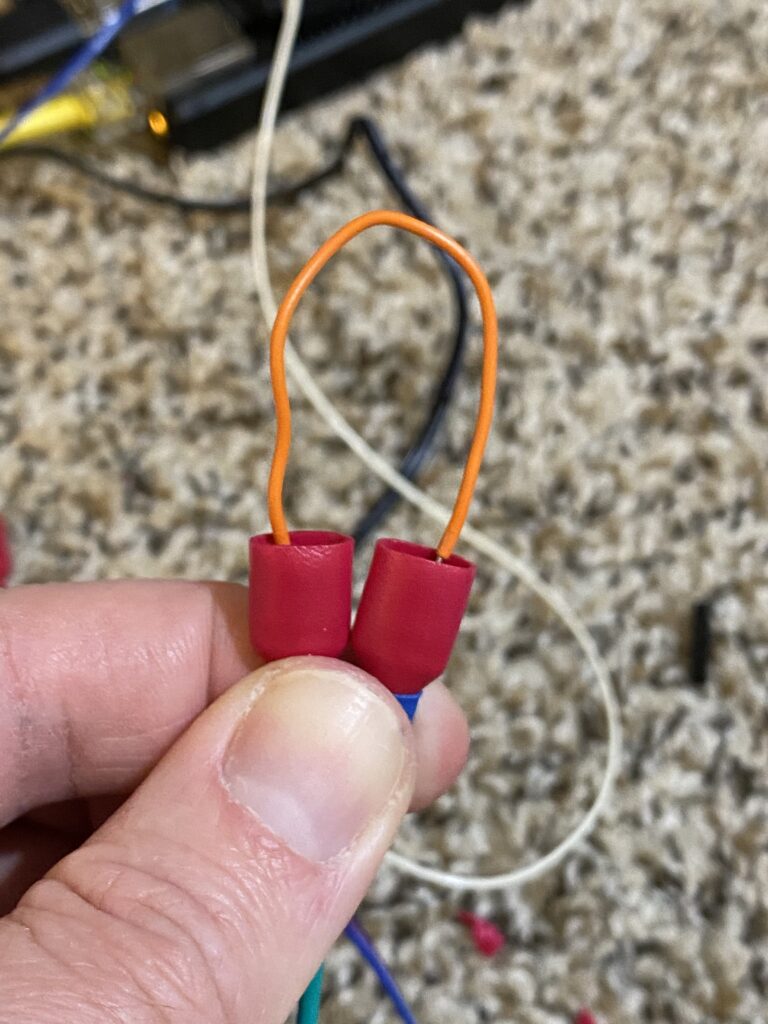
- Each of the coin buttons are evenly spaced in my CAD design, and I cut multiple wires of the same length: 20 Centimeters, including for receiving the power supply.
- With 4 buttons in a parallel circuit, you’ll need to cut a total of 8 wires.
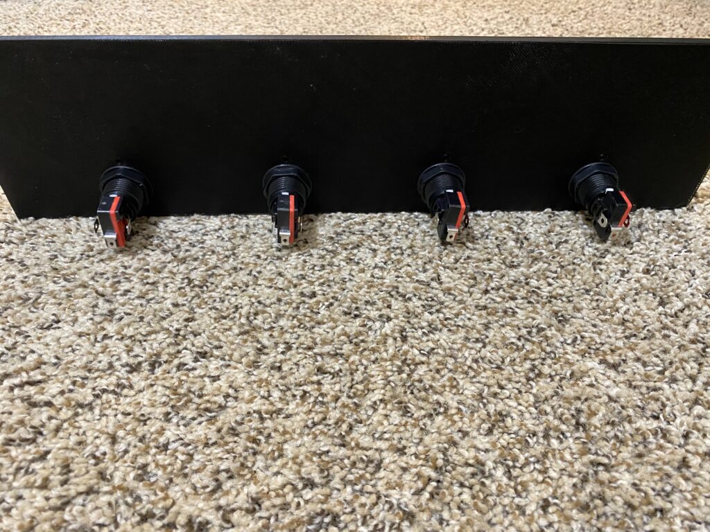
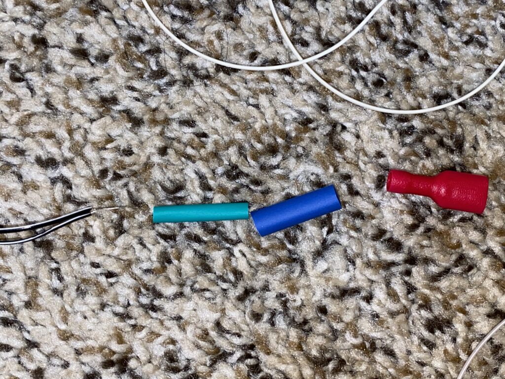
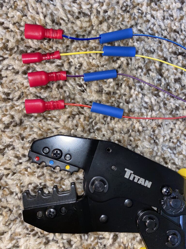
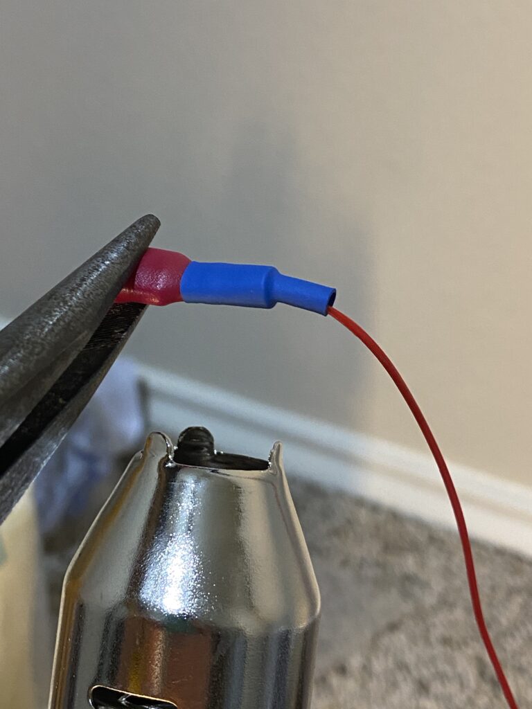
The terminals are all the same size, but, the colors represent a different gauge of wire that will fit in them.
This was a personal preference for keeping track of polarity, but not something that I’d recommend if you don’t have a good terminal crimper.
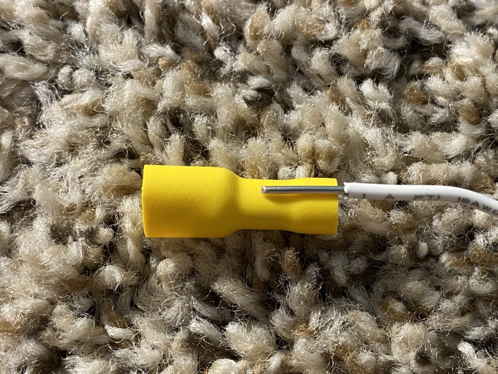
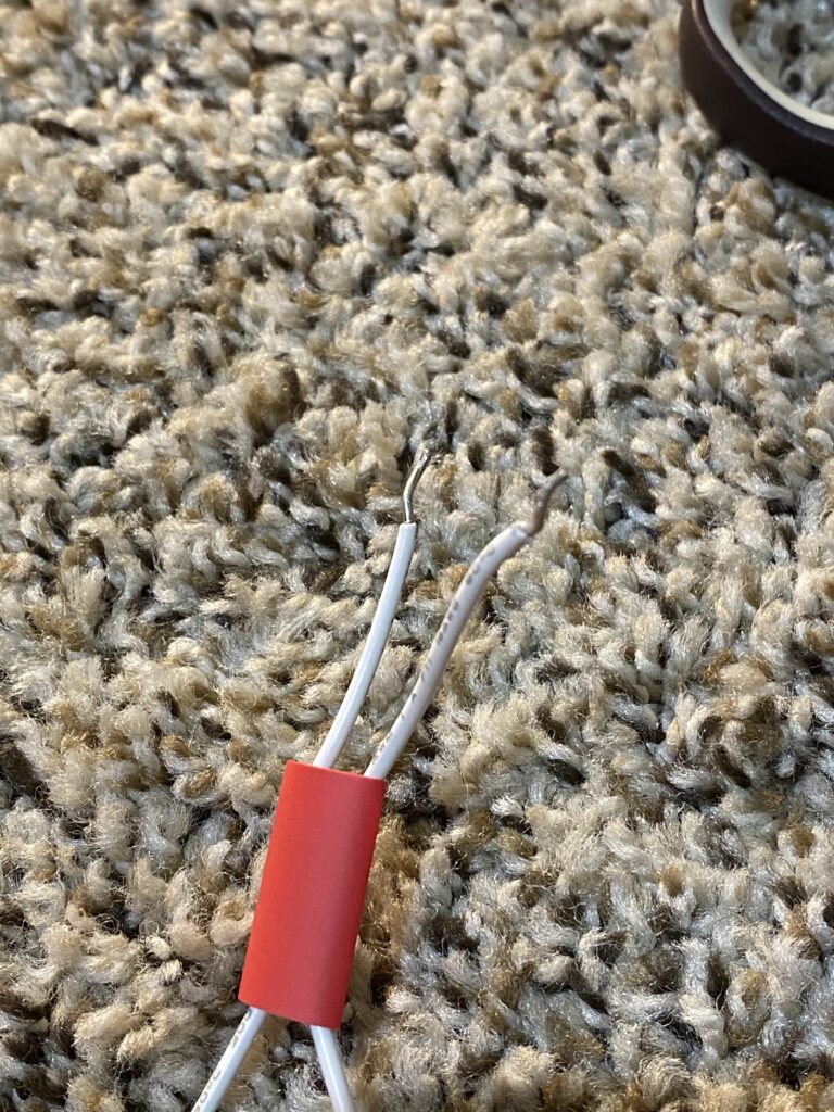
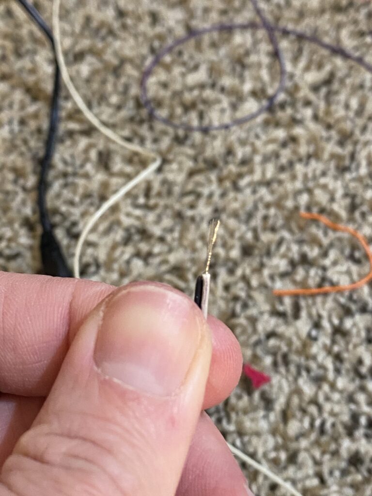
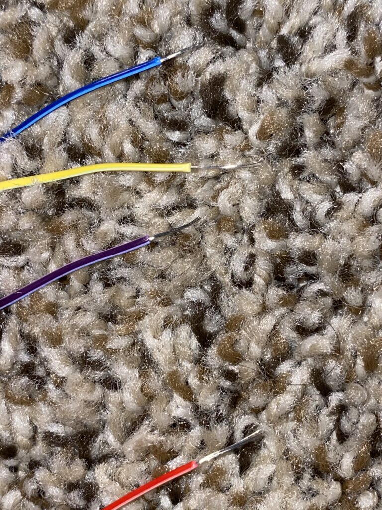
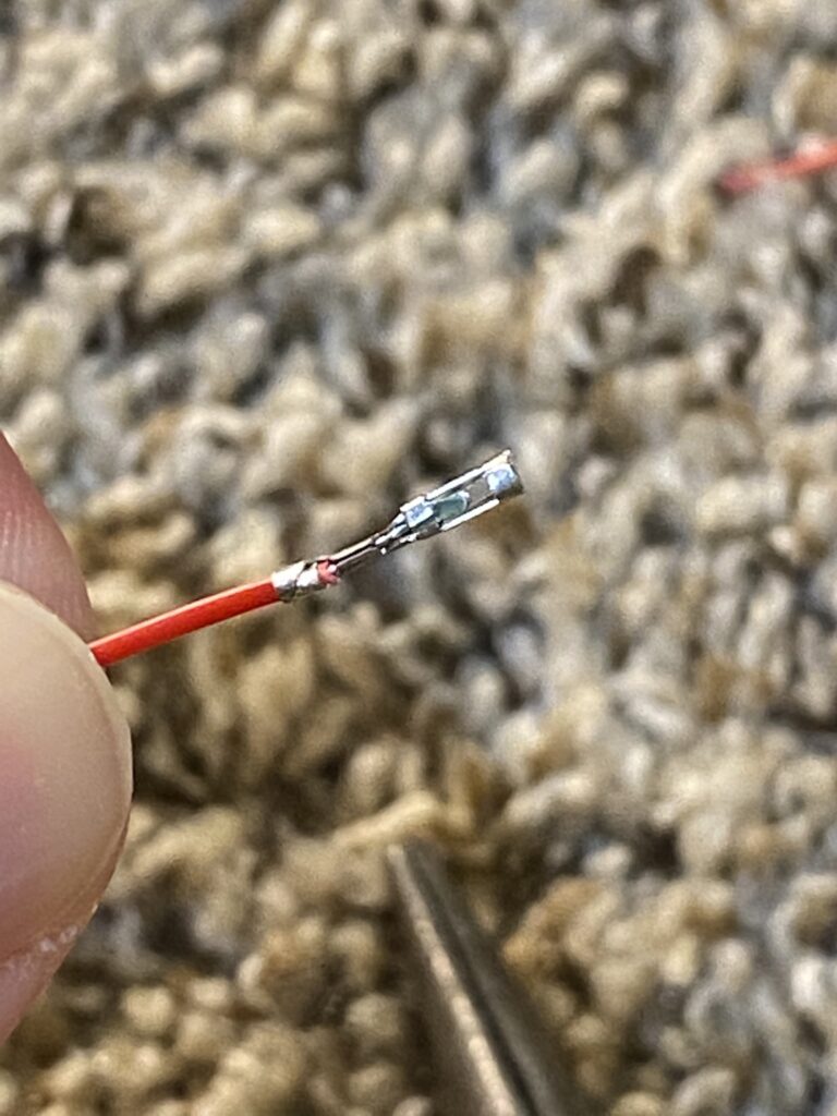
- I measured how much of the wire would be exposed inside the connector, stripped it, and then stripped the rest of the cords tips to match my initial stripped wire.
- Initially, I used heat-shrink out of habit, but the crimper worked fine — I shouldn’t have wasted my time with the heat-shrink.
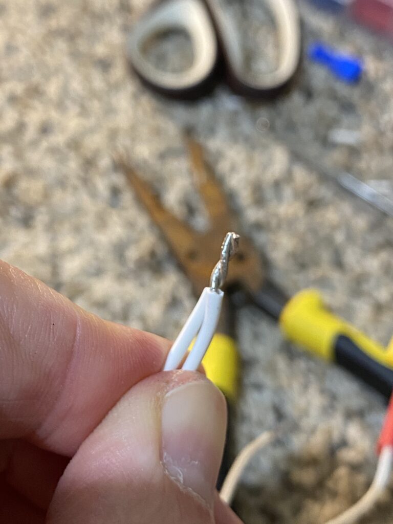
- I used my electrical pliers to twist the wires together for parallel and then inserted them into the reciprocal terminal, crimped it, and moved onto the next one.
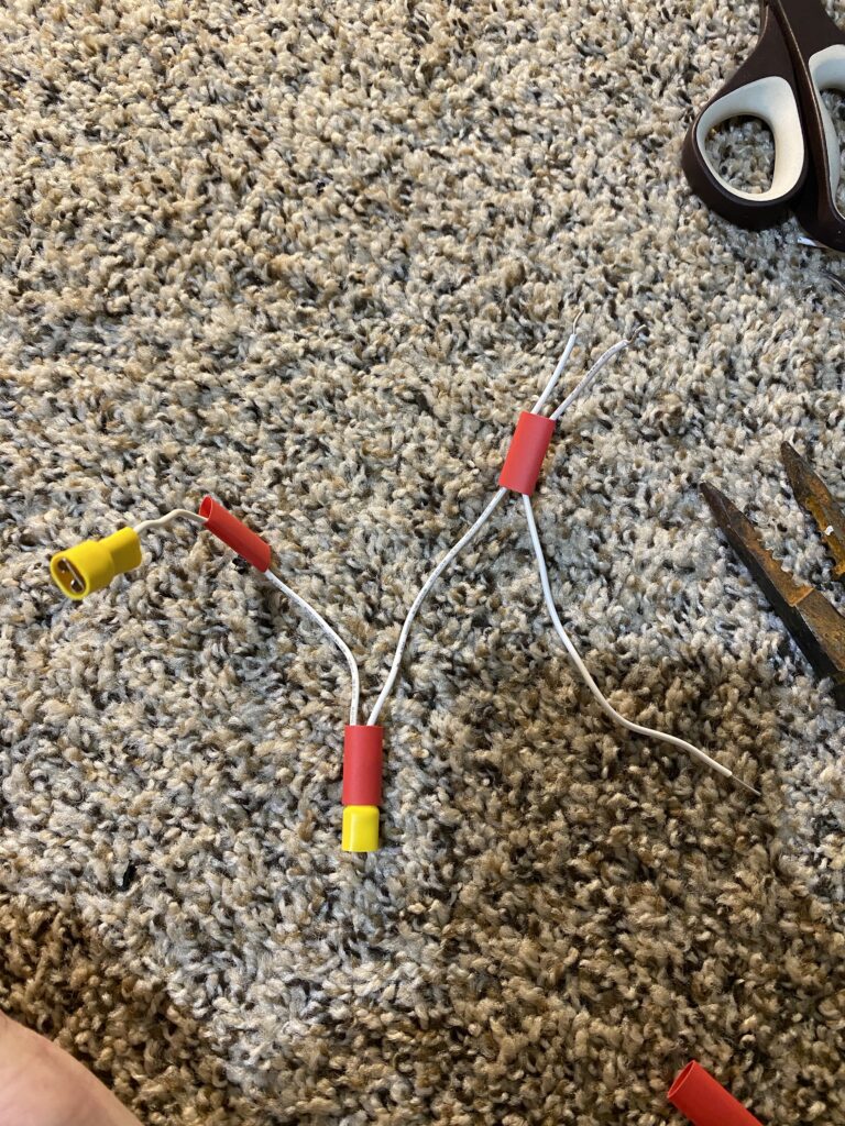
- The positive side connects to the side of the LED with the inline resistor which is denoted with a double-loop.
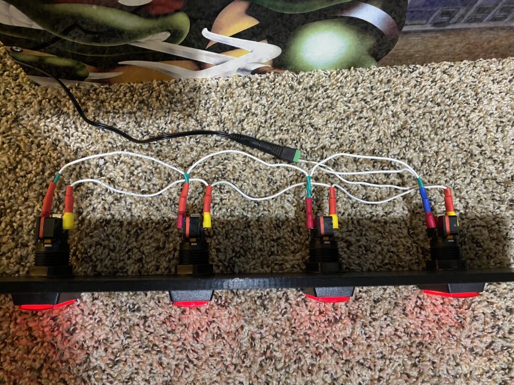
- After completing each of the power connections to the buttons, I connected the Female 12v DC Power Jack and used an eyeglasses screwdriver to tighten the terminals down onto the wires.
- I then took the 12V 1A adapter that came with the control deck and plugged it into the terminal to ensure that each light came on.
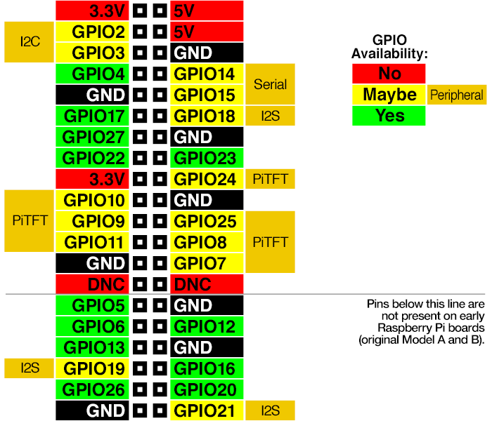
For the next section of this article, you should familiarize yourself with this image by Adafruit from the Adding Controls: Hardware section of their Retro Gaming with Raspberry Pi article by Phillip Burgess.
Please note: newer Raspberry Pi models have internal resistors, which is why you don’t need to add them inline with your buttons.
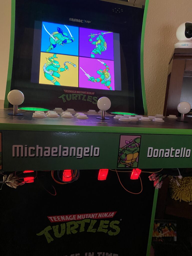
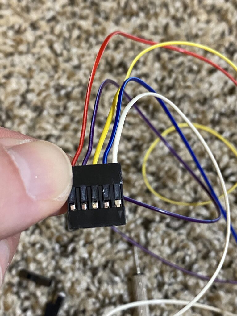
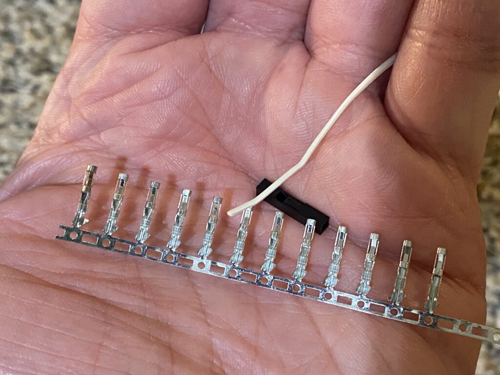
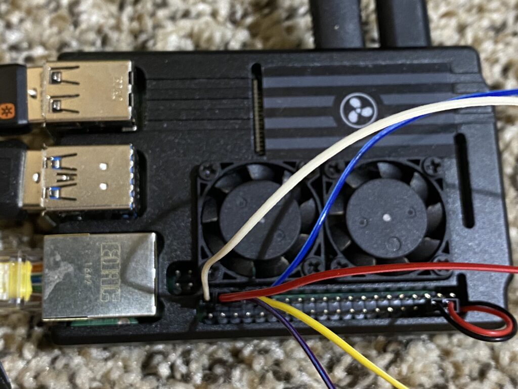
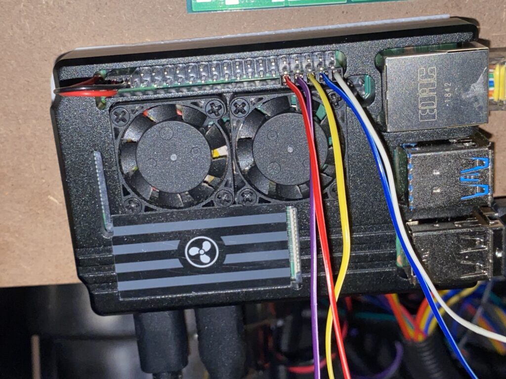
I made a 5-pin header that uses the following pins at the bottom left:
- GPIO 6: Raphael coin acceptor
- GPIO 13: Donatello coin acceptor
- GPIO 19: Michelangelo coin acceptor
- GPIO 26: Leonardo coin acceptor
- GND: Common ground wire shared between all coin buttons.
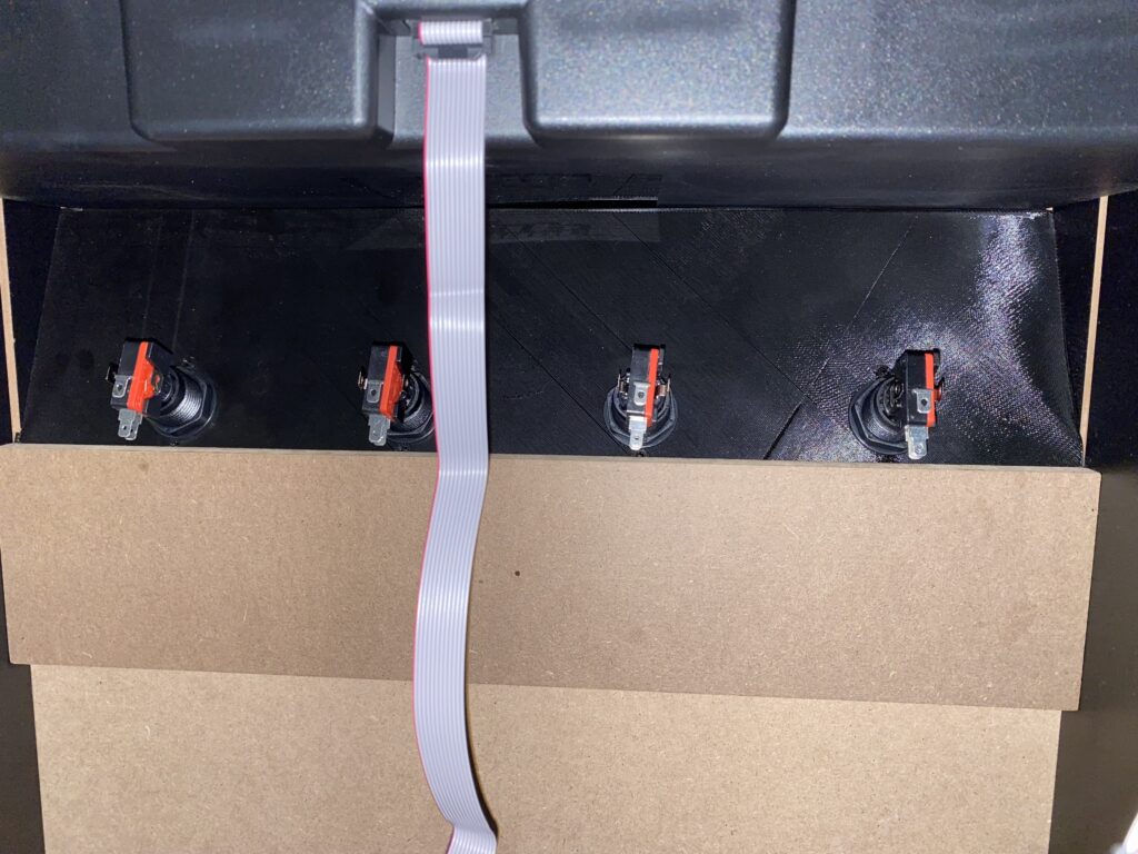
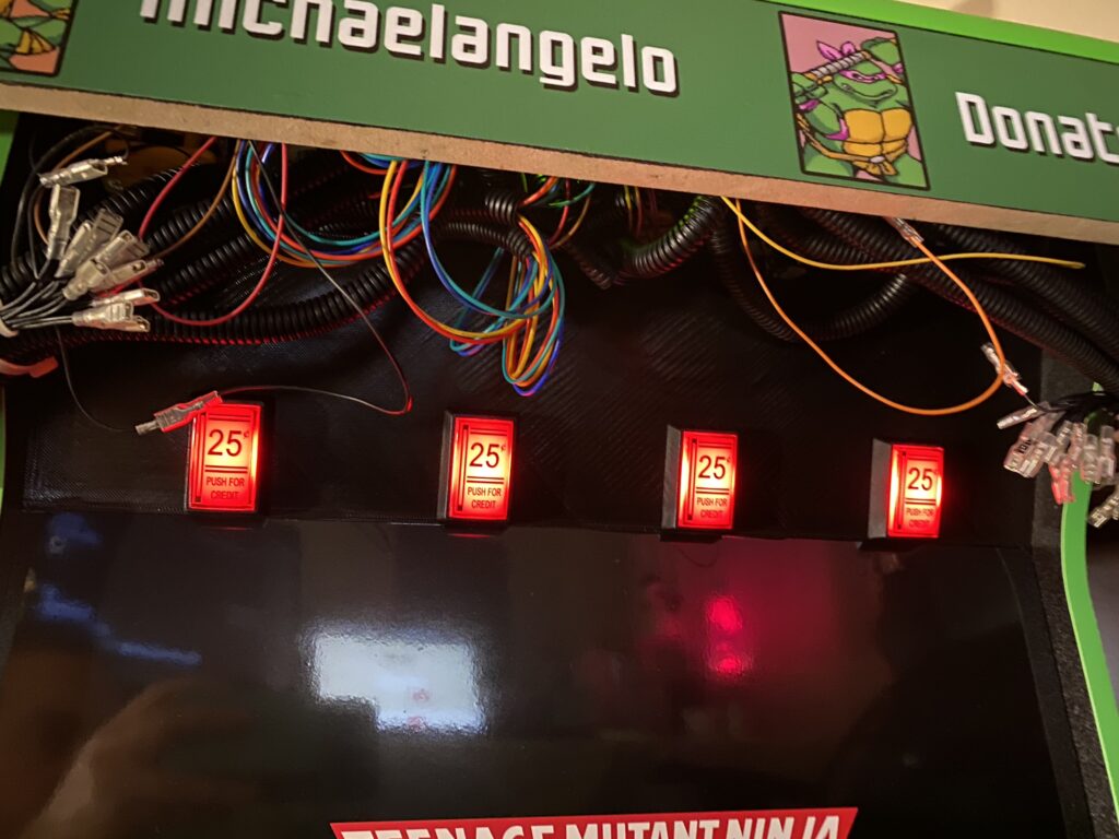
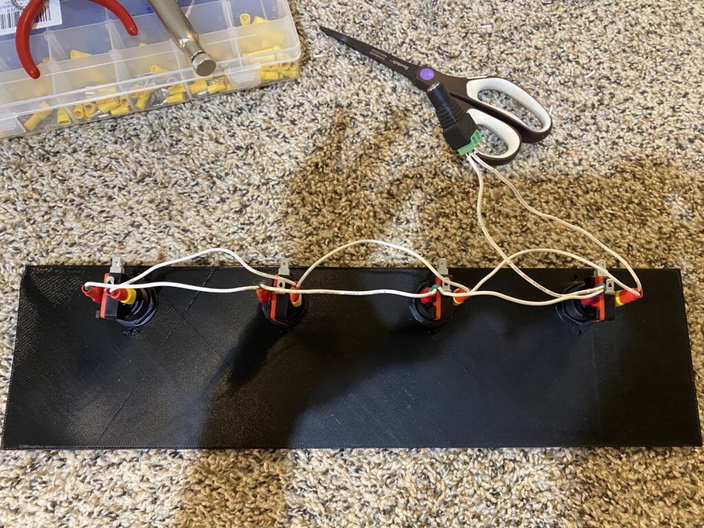
I used seamstress tape to measure the distance from the mounted buttons to the back of the monitor, which ended up being 50 centimeters. Since the ribbon cable has multiple wires that run parallel to each other, this 50 CM cut was more than enough to create a parallel, common ground wire (which required two of these wires — I used black and white), as well as all of the coin buttons, with leftover that I can save for other uses (e.g. adding more inputs to this machine at a later date, such as service buttons).
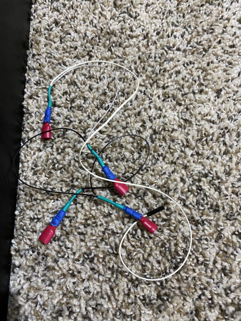
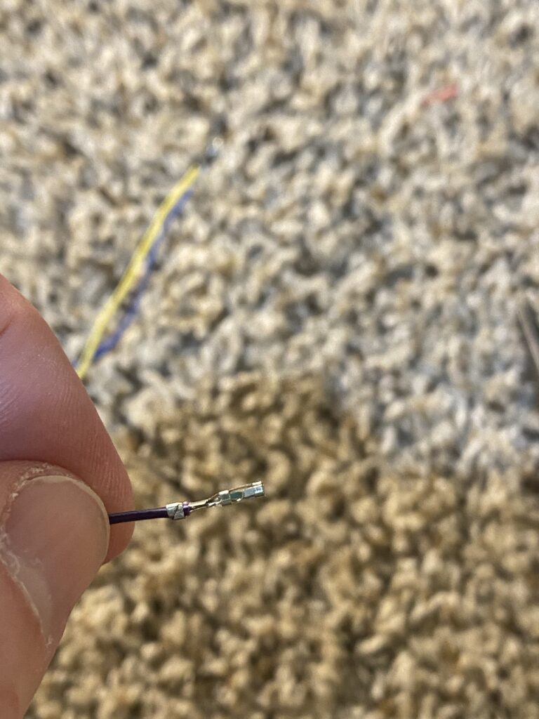
- Since these wires are so small, I did in fact use heat-shrink to secure them to the terminal connectors. I ended up having to use two separate sizes of heat-shrink to create a snug fit, where the larger piece fit around the crimped terminal, then the smaller heat-shrink around the wire and the larger heat-shrink. So far, this has held up to my tugging on it, as well as light snags when I installed the controls.
- You will want to create a parallel ground wire in the same manner that you created parallel circuits for the 12V power for the LEDs.
- Add a pin to the end of the common ground wire, but hold off on pressing it into the plastic header. It’s easier to test (including placing on/pulling from the GPIO) before you lock it into the plastic header.
- If you have a multimeter, you can perform a continuity test.
- Just like the grounds, each of the signal wires has a terminal on one side for the button, and a header pin on the other side that connects to the Raspberry Pi’s GPIO pins.
- 5 pins are easier to place (and pull) as a single piece, which is why I ended up combining them into a single header. Again, hold off on pressing these into the header until you test their connection on the software side (and/or continuity test with a multimeter).
- Following the chart from above, any available GPIOs and a single ground pin can be used, but I opted for pins that were all together (including ground) with the added bonus of being furthest away from voltage pins.
Adafruit’s Retrogame
Using SSH, copy and paste the following commands into your Raspberry Pi’s terminal, including the curly brackets. The Retrogame installer script will then run. It doesn’t matter what configuration you choose (I selected 1 for PiGRRL 2 controls), because you’ll overwrite the file with one that’s specific to these Coin Insert buttons. After Retrogame is installed and setup, it will ask you to reboot, go ahead and do so.
{

cd

curl \
    https://raw.githubusercontent.com/adafruit/Raspberry-Pi-Installer-Scripts/master/retrogame.sh \
    >/tmp/retrogame.sh \
    ;

sudo bash /tmp/retrogame.sh

}
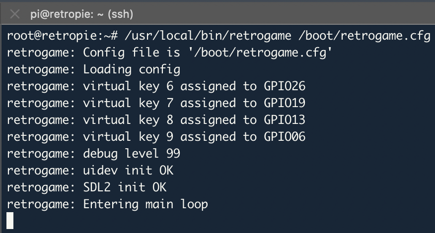
After the system reboots, overwrite the /boot/retrogame.cfg file with the configuration file from the Teenage Mutant Ninja Terminals Git repository. The changes take effect without needing to restart the Retrogame process (located at /usr/local/bin/retrogame). Retrogame is normally started by rc.local (more information here) after successful boot, and all output is discarded in the background. For testing each of the inputs, stop the Retrogame process and then launch it manually, and information about Retrogame’s configuration will appear:
{

pkill retrogame

/usr/local/bin/retrogame /boot/retrogame.cfg

}
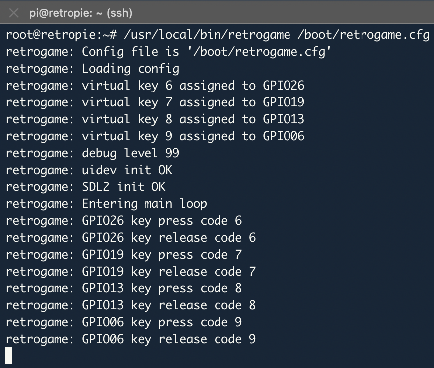
When coin insert buttons are pressed, messages such as these will appear.
Everything is connected, you’ve setup the configuration file, and you know what it looks like when it works. My process was:
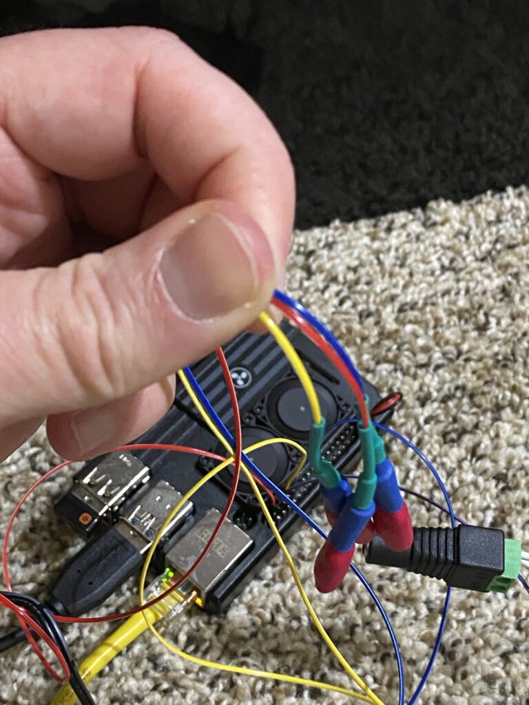
- Take the female pins (before mounting them in the header) and plug them onto the male GPIO pins.
- Take each of your GPIO pins, and with a jumper (spare wire or any other conductive material) connect the terminal to the ground.
- I started with GPIO 26 (Leonardo / Coin 1) and briefly connected it to the first ground closest in the circuit to the pin and then moved down the line of the common ground wire and its terminals.
- Then, I did the same for GPIO 19 (Michelangelo), GPIO 13 (Donatello), and GPIO 6 (Raphael). This makes a total of 16 tests, and while it’s tedious, will help you locate any errors (I actually did find errors, and had to re-crimp).
- Once you’ve tested and ensured that all of the connections work, it’s time to push the female pins into the header.
- I’ve found that the easiest (and quickest) way is to push the bulk of the pin into the header, and then use the flat-head side of the eyeglasses screwdriver to push the rest of it in, while taking care to not fray the electrical wire. You’ll hear/feel a small snap, and can see that the metal fin of the pin protrudes enough to catch under the plastic. You can tug on the wire, and the female pin should stay in the header. Repeat this process 4 more times and you now have a 5-pin header that’s ready to slide onto the GPIO.
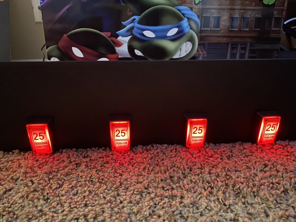
- Press each of the lit-up buttons, and you should see a message appear, indicating it being pressed and subsequently released.
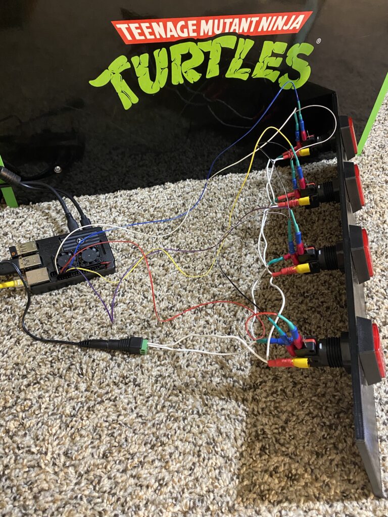
- If all goes according to plan, you’re now ready to disconnect the coin buttons and Raspberry Pi, mount everything, and connect everything together in a more permanent manner.
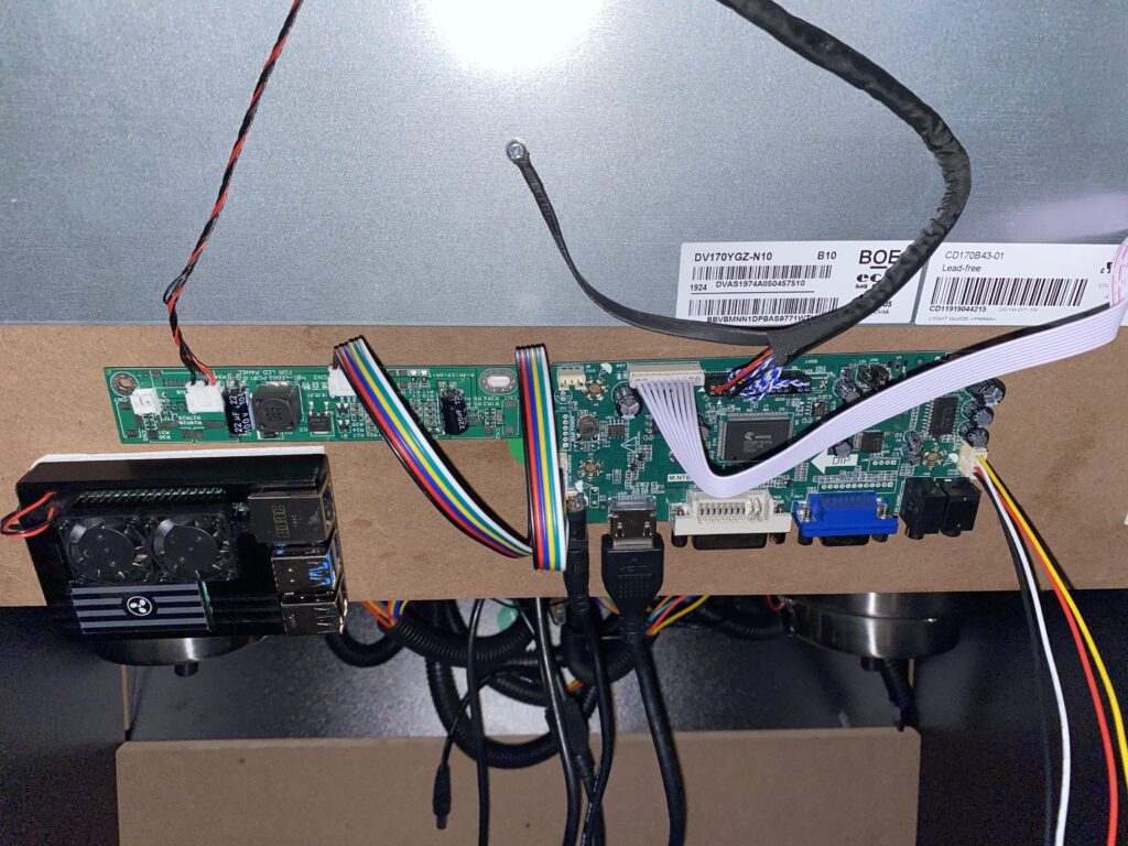
- 2 strips of 3M tape provides for a solid mount of the Raspberry Pi case to the back of the monitor.
- Slide the 3-D printed piece in where the original “J” piece was, and on top of the “I” piece.
- Connect the 5-pin header to the Raspberry Pi’s GPIO pins — please take care to plug into the correct position, and not the 3.3 or 5V powered positions!
- Plug in the spare plug from the cup holder LEDs to the 12-Volt parallel circuit that you made for the lights.
Assuming that you have your SSH window still open, you should be able to push each of the illuminated buttons and see results in the terminal. If so, you can shut the Raspberry Pi down (sudo shutdown --poweroff now) and move on to the next page.
This is video of results that we’re heading towards with these coin buttons tied to the GPIO interrupts: